Jacking buffer device capable of automatically regulating

An automatic adjustment and cushioning device technology, which is applied in the direction of transportation and packaging, conveyor objects, etc., can solve the problems of different compression distances of shock-absorbing materials and inaccurate positioning of manipulators, so as to reduce the hidden danger of bumping, reduce the distance, and reduce the moving path Effect

Pending Publication Date: 2020-09-04
NINGXIA KOCEL MACHINE TOOL ACCESSORIES
View PDF0 Cites 0 Cited by
  • Summary
  • Abstract
  • Description
  • Claims
  • Application Information

AI Technical Summary

Problems solved by technology

However, the problem of using shock-absorbing materials with large shrinkage is that workpieces of different weights will cause different compression distances of the shock-absorbing materials, that is, the falling distance of each workpiece is different. Small shock-absorbing material, but cannot completely avoid bruising or damage

Method used


Image

  • Jacking buffer device capable of automatically regulating
  • Jacking buffer device capable of automatically regulating
  • Jacking buffer device capable of automatically regulating

Examples


Embodiment 1

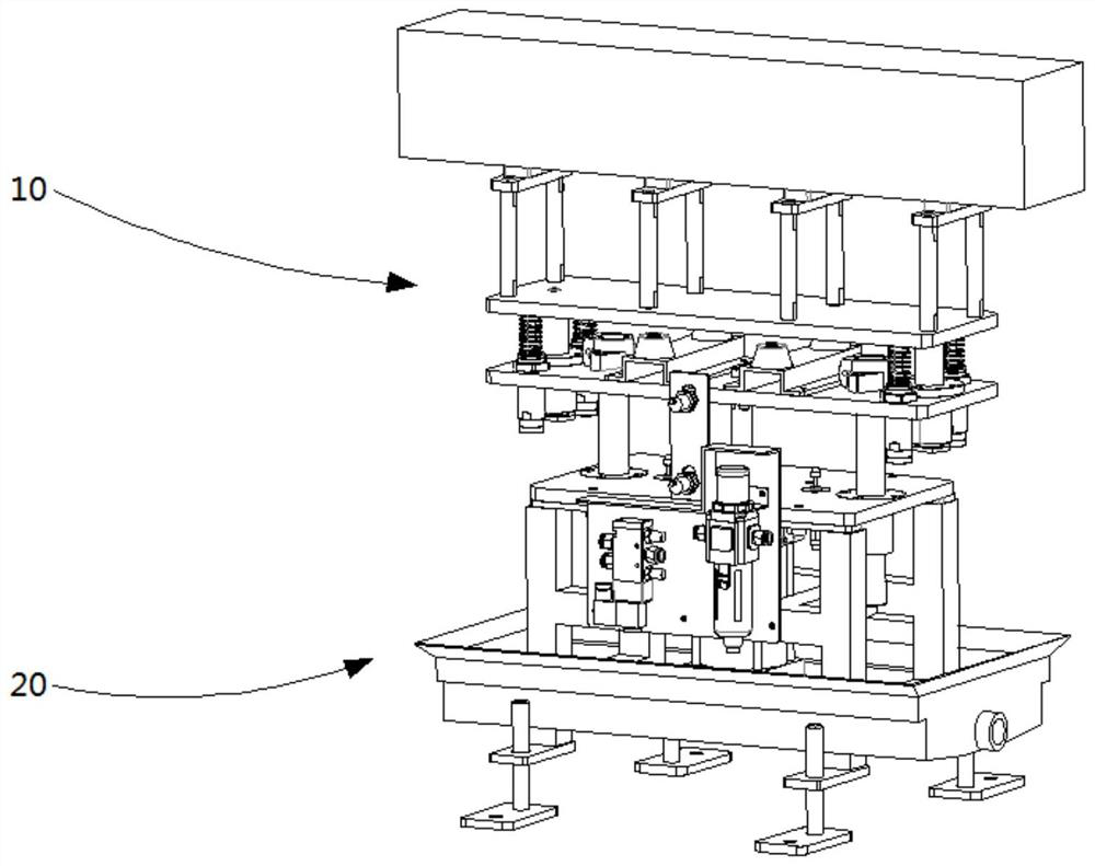
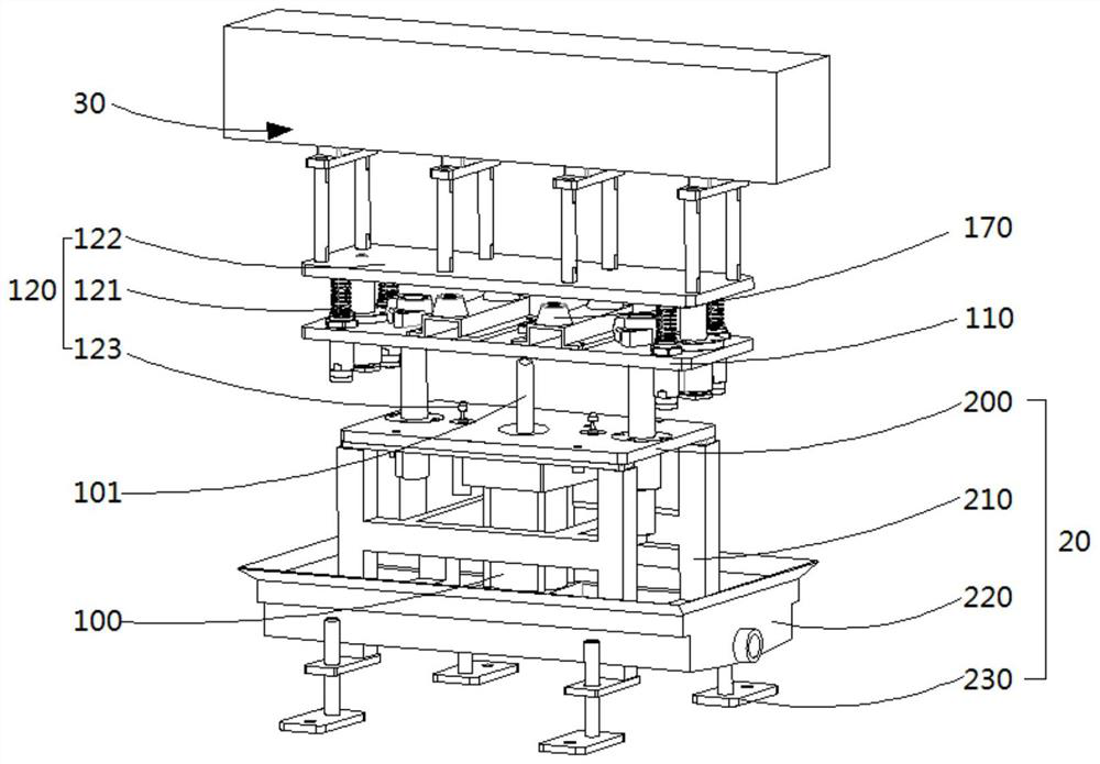
[0033] see figure 1 and figure 2 , The automatic adjustment jacking buffer device 10 is installed on the frame 20 . The frame includes a base plate 200, a support 210, a water tray 220, and several supports 230. The base plate is installed on the top surface of the support 210 as an installation reference for the automatic adjustment of the lifting buffer device; the supports 230 are installed at the bottom of the support and arranged at intervals for The support adjustment bracket; the water receiving tray 220 is located between the base plate and the support, and is fixed around the support, and is used to centrally receive the liquid carried by the workpiece. The automatic jacking buffer device 10 includes a driving member 100 , a jacking plate 110 , an adjustment assembly 120 , and a control assembly; the adjustment assembly includes a damping buffer 121 , a floating plate 122 , and a hydraulic buffer 123 . In this embodiment, the driving part is replaced by a cylinder,...

Embodiment 2

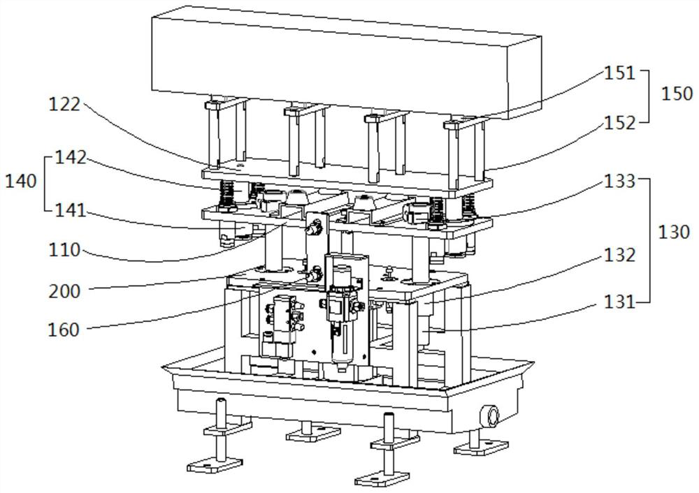
[0036] Refer to attached image 3 As shown, in order to ensure the stable vertical operation of the floating plate and avoid the tilting of the workpiece after being placed, the present invention also provides a second guide assembly 140 . One end of the second guide assembly is connected to the lifting plate 110 , and the other end is connected to the floating plate 122 . Specifically, the second guide assembly includes a bearing 141 and a T-shaped shaft 142 . The bearing passes through the lifting plate and is fixed on the lifting plate, the small end of the T-shaped shaft is embedded in the bearing and the protruding bearing is arranged, and the protruding end is screwed with the floating plate.

[0037] It should be noted that at least two groups of the first guide assembly and the second guide assembly are respectively provided. In order to ensure the jacking force of the cylinder and the balance of the jacking plate, floating plate, etc., it is best to set an even number...

Embodiment 3

[0039] Refer again to the attached image 3 As shown, on the basis of the first embodiment, a shock absorbing mechanism 150 is arranged on the floating plate. The shock absorbing mechanism includes a contour column 151 and a buffer bar 152, the contour column is fixed on the floating plate, the buffer bar is installed on the contour column, and the workpiece is placed on the buffer bar. The buffer strip can be a nylon strip or a rubber strip, and any elastic material with shock absorption and cushioning can be used, which is not specifically limited in this embodiment. In order to further ensure that the workpiece is placed on the buffer bar without contact scratches and the workpiece is placed stably, the contact surface between the buffer bar and the workpiece is set as a discontinuous surface. As shown in the figure, there are 8 intervals of contour columns and 4 buffer bars, which can be flexibly designed according to specific working conditions in practical applications....


PUM


Abstract

The invention discloses a jacking buffer device capable of automatically regulating, and the jacking buffer device is mounted on a framework. The jacking buffer device comprises a drive part, a jacking plate, a regulating assembly and a control assembly, wherein the regulating assembly comprises a buffer and a floating plate; the drive part is fixedly arranged in the framework, and the output endof the drive part is bulged out of the top surface of the framework; one surface of the jacking plate is connected to the output end of the drive part; one surface of the buffer is connected to the floating plate, and the other surface of the buffer is connected to the other surface of the jacking plate; and the control assembly is electrically connected to the buffer. The buffer outputs a matchedstroke through workpiece weight inducted by the control assembly, so that gripper workpiece placing and gripper workpiece gripping are performed at the same height, and therefore, positioning precision of a gripper is improved, a distance between a workpiece placing position and the floating plate further can be reduced to the greatest extent, and a workpiece is prevented from being damaged.

Description

technical field [0001] The invention is mainly applied to the buffering and receiving of materials during the feeding process of a manipulator. Background technique [0002] The manipulator is used for loading and unloading workpieces in the batch processing production process, and its action of grabbing and placing workpieces is essential. After finishing or the workpiece with a brittle material, it is the most basic requirement to handle it gently and slowly to prevent damage. However, when the manipulator puts the workpiece, it cannot release the gripper after the workpiece is in zero-distance contact with the placement platform, but always maintains a certain distance, releases the gripper, and the workpiece has a short-distance free fall process. It will lead to the risk of bruising or damage to some finished parts. [0003] Conventional shock-absorbing buffer method is to use shock-absorbing material at present. However, the problem of using shock-absorbing material...

Claims


Application Information

Patent Timeline
IPC IPC(8): B65G47/74B65G47/90
CPCB65G47/74B65G47/90
Inventor 苟牛红蒋发根齐亚文陈翔宇周永华虎岩
Owner NINGXIA KOCEL MACHINE TOOL ACCESSORIES
Why Eureka
Try Eureka