
Irrigation district water demand metering and monitoring method and system

A monitoring system and water demand technology, applied in computing, instrumentation, data processing applications, etc., can solve the problems of waste of resources, large labor input, and large randomness, and achieve the goal of improving operating efficiency, rationalizing water allocation, and reducing operating costs. Effect

Pending Publication Date: 2020-09-04
珠海智信佰达科技有限公司
View PDF14 Cites 4 Cited by
  • Summary
  • Abstract
  • Description
  • Claims
  • Application Information

AI Technical Summary

Problems solved by technology

[0002] At present, most of the irrigation operations in my country's irrigation areas are still in the traditional irrigation mode: mainly manual control, relying too much on human experience, lack of data support, large randomness, personnel need to go to the site to check the irrigation situation, and the manpower investment is large, time-consuming, and not timely. , and there is no scientific data support in the whole process, resulting in random irrigation water, waste of resources, and long-term randomness will aggravate the damage of soil structure
[0003] The irrigation plans of many irrigation areas are based on years of accumulated experience, forming a fixed irrigation pattern, unable to adapt to flexible and changeable irrigation methods, and unable to comprehensively verify the rationality of irrigation plans

Method used


Image

  • Irrigation district water demand metering and monitoring method and system
  • Irrigation district water demand metering and monitoring method and system
  • Irrigation district water demand metering and monitoring method and system

Examples


Embodiment

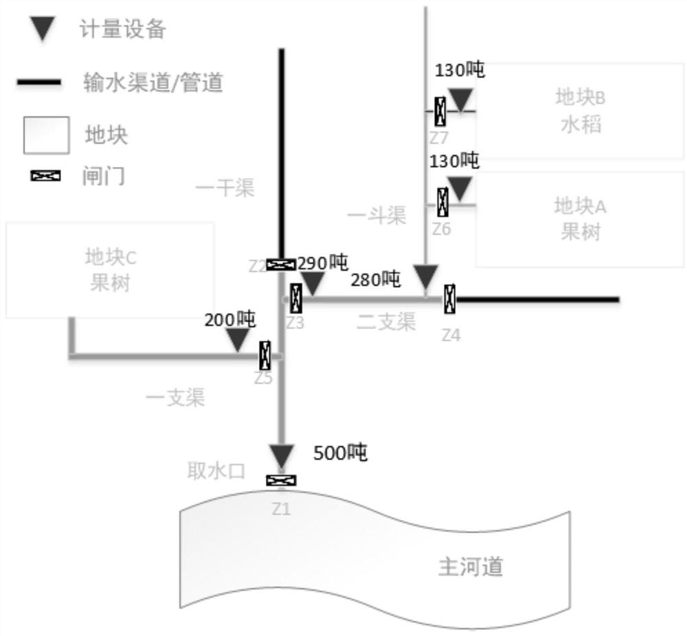
[0104] refer to Figure 5 ,Such as Figure 5 As shown, a logical model of irrigation district designed in this embodiment. Taking the water intake 1 of the main river as the water source of the irrigation area, the water flows through the main gate 2 of the main canal, and the water passing through the main gate 2 of the main canal is automatically metered by the flow metering device 3 of the main canal. The metering equipment is determined according to the mode of the channel. For example, if it is a pipeline, it can be measured by an electromagnetic flowmeter, and if it is a gate, it can be measured by a water level difference. The measurement method of other branch canals, bucket canals and agricultural canals is similar to that of the main canal, and measures should be taken according to local conditions.

[0105] The user first needs to initialize the element information and parameters of the irrigation area, mainly including the initialization of the spatial informatio...


PUM


Abstract

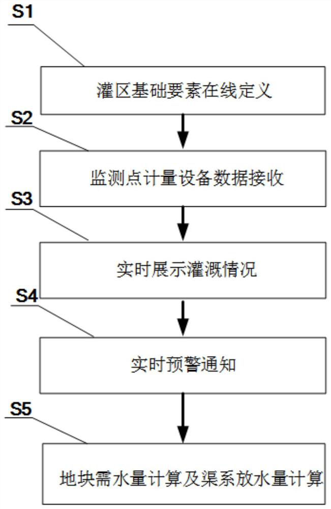
The invention discloses an irrigation district water demand metering and monitoring method and system, and relates to agricultural irrigation water demand metering, and the method comprises the steps:dynamically and automatically calculating the water discharge capacity of each canal system according to the field water demands of different planting crops in different periods; through the water volume metering devices installed on the canal systems, dynamically monitoring the irrigation water volume condition, reminding managers of closing gates at what time in time, and forming reasonable irrigation plans for different periods, different crops and different land parcels. Irrigation operation of the irrigation area is guided, and a big data warehouse for automatic irrigation of the irrigation area is formed. According to the method, real-time sharing of irrigation district information resources is realized, the operation efficiency of the irrigation district is improved, and the operation cost of the irrigation district is reduced. A scientific decision basis is provided for an irrigation district management department, finally irrigation district management informatization, waterallocation rationalization, water measurement accuracy and charging standardization are achieved, and a technical guarantee is provided for achieving efficient modern agriculture.

Description

technical field [0001] The invention relates to measurement of water demand for agricultural irrigation, in particular to a method and system for measuring and monitoring water demand in an irrigation area. Background technique [0002] At present, most of the irrigation operations in my country's irrigation areas are still in the traditional irrigation mode: mainly manual control, relying too much on human experience, lack of data support, and randomness. Personnel need to go to the site to check the irrigation situation, and the manpower investment is large, time-consuming, and not timely. , and there is no scientific data support in the whole process, which leads to random irrigation water, waste of resources, and long-term randomness will aggravate the damage of soil structure. [0003] The irrigation plans of many irrigation areas are based on years of accumulated experience, forming a fixed irrigation pattern, unable to adapt to flexible and changeable irrigation method...

Claims


Application Information

Patent Timeline
IPC IPC(8): G06Q50/02
CPCG06Q50/02
Inventor 李强王卓
Owner 珠海智信佰达科技有限公司
Learn More