Eureka AIR delivers breakthrough ideas for toughest innovation challenges, trusted by R&D personnel around the world.

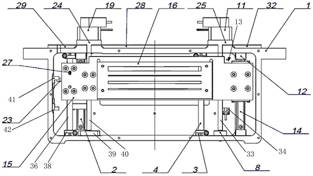
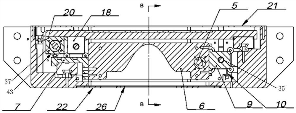
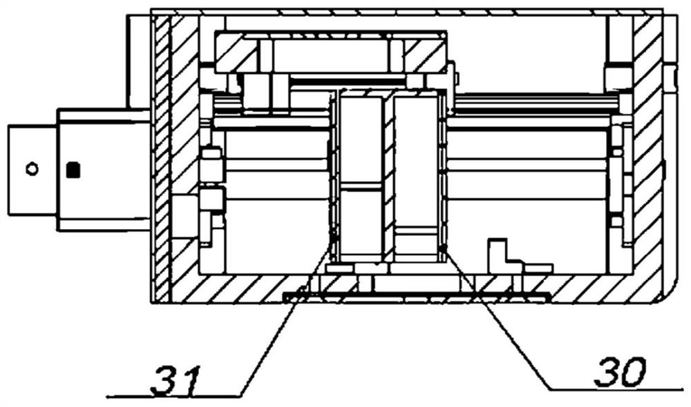
Front collimator suitable for low-dose radiation of CT equipment and CT equipment

A pre-collimator and collimator technology, which is applied in the directions of instruments used for radiological diagnosis, use of diaphragms/collimators, and control of radiological diagnostic equipment, can solve the problem of low X-ray collimation accuracy and increase patient radiation. Dosage, unreasonable design structure, etc., to ensure low leakage, ensure installation accuracy, and protect health

Inactive Publication Date: 2020-09-08
SHANDONG DACHENG MEDICAL TECH CO LTD
View PDF1 Cites 2 Cited by
  • Summary
  • Abstract
  • Description
  • Claims
  • Application Information

AI Technical Summary

Problems solved by technology

[0002] The front collimator assembly of CT equipment plays a key role in the CT equipment. The front collimator includes a filter device made of absorbing material for weakening and changing the spectral composition of X-ray radiation and an X-ray collimation device. Different slits are designed on the front collimator. By changing the size of the slits, the scanning layer thickness of the CT equipment can be controlled; at the same time, it can shield the X-rays outside the scanning field of view of the CT equipment to prevent invalid X-rays. X-rays and stray X-rays are detected by the detector system, causing troubles for subsequent data processing, but the collimation accuracy of X-rays in the prior art is not high, the shielding effect is not good, and there is X-ray leakage, which increases the patient's time in the hospital. Radiation dose when receiving CT

Method used


Image

  • Front collimator suitable for low-dose radiation of CT equipment and CT equipment
  • Front collimator suitable for low-dose radiation of CT equipment and CT equipment
  • Front collimator suitable for low-dose radiation of CT equipment and CT equipment

Examples


Embodiment Construction

[0088] The present invention will be described in detail below in conjunction with specific embodiments. The following examples will help those skilled in the art to further understand the present invention, but do not limit the present invention in any form. It should be noted that those skilled in the art can make several changes and improvements without departing from the concept of the present invention. These all belong to the protection scope of the present invention.

[0089] The invention provides a kind of CT equipment, such as Figure 4 As shown, it includes an X-ray tube 100, a front collimator 200, an inverter 300, a high voltage generator 400, a detector data acquisition system 500, a linear power supply assembly 600, a heat exchanger 700, a counterweight device, and a fixed counterweight assembly 1000 and a rotating base plate 1100; a front collimator 200, an inverter 300, a high voltage generator 400, a detector data acquisition system 500, a linear power supp...


PUM


Abstract

The invention provides a front collimator suitable for low-dose radiation of CT equipment and the CT equipment, and relates to the technical field of medical equipment. The CT equipment comprises an X-ray tube, the front collimator, an inverter, a high voltage generator, a detector data acquisition system, a linear power supply assembly, a heat exchanger, a counterweight device, a fixed counterweight assembly and a rotating substrate; the front collimator comprises an X-ray collimator frame, an X-ray filtering device, an X-ray filtering driving device, an X-ray collimation device, an X-ray collimation driving device and an X-ray shielding device; and the front collimator is located below the X-ray tube and adopts integrated design, an X-ray tube filtering device and the X-ray collimation device are located in the X-ray collimator frame at the same time, and all assemblies of the front collimator are convenient to install, detach and maintain. According to the invention, collimation andshielding of X-rays can be achieved, the low leakage rate of the X-rays is ensured, and the body health of medical staff is protected.

Description

technical field [0001] The invention relates to the technical field of medical equipment, in particular to a front collimator suitable for low-dose radiation of CT equipment and CT equipment. Background technique [0002] The front collimator assembly of CT equipment plays a key role in the CT equipment. The front collimator includes a filter device made of absorbing material for weakening and changing the spectral composition of X-ray radiation and an X-ray collimation device. Different slits are designed on the front collimator. By changing the size of the slits, the scanning layer thickness of the CT equipment can be controlled; at the same time, it can shield the X-rays outside the scanning field of view of the CT equipment to prevent invalid X-rays. X-rays and stray X-rays are detected by the detector system, causing troubles for subsequent data processing, but the collimation accuracy of X-rays in the prior art is not high, the shielding effect is not good, and there i...

Claims


Application Information

Patent Timeline
IPC IPC(8): A61B6/03G21K1/02
CPCA61B6/032A61B6/4035A61B6/54G21K1/02
Inventor 陈牧苏士刚
Owner SHANDONG DACHENG MEDICAL TECH CO LTD
Why Eureka
Eureka Blog
Learn More