Steel pipe necking machine

A closing machine and steel pipe technology, which is applied in the field of water conservancy projects, can solve the problems that the closing device is bulky, cannot be easily plugged and connected, and is not convenient for mobile use on the construction site, and achieves the effect of simple and convenient operation

Inactive Publication Date: 2020-09-08
徐州易尚饰家装饰工程有限责任公司
View PDF7 Cites 0 Cited by
  • Summary
  • Abstract
  • Description
  • Claims
  • Application Information

AI Technical Summary

Problems solved by technology

[0002] At present, in water conservancy construction, it is often necessary to connect pipe fittings to each other. However, due to the technological defects in the production and processing of pipe fittings and the mutual extrusion deformation during transportation and handling, there will be certain tolerances in their wall thickness, inner and outer diameters, and ellipticity. , so that the fit is too tight during the plug-in connection, and the plug-in connection cannot be easily performed. However, the existing pipe fitting closing machine is large in size and high in cost, and cannot be conveniently moved and used in on-site construction.
[0003] The notification number CN107497953A discloses an automatic closing device for steel pipe diameter reduction, including a frame, and a propulsion cylinder, a diameter reduction die and a clamping die arranged on the frame, the propulsion cylinder is connected with the diameter reduction die, And it is used to push the reducing die to extrude the steel pipe fixed on the clamping die to realize the diameter reduction of the steel pipe. The clamping die includes at least one set of clamping units and driving cylinders, and each set of clamping units consists of upper and lower parts It is composed of splints connected with the drive cylinder respectively, and forms a clamping cavity for placing the steel pipe to be processed. The end of the clamping cavity is also provided with a baffle for resisting the steel pipe. The PLC controller of the driving cylinder and the propulsion cylinder, the closing device is large in size and high in cost, and it is not convenient for mobile use on the construction site

Method used


Image

  • Steel pipe necking machine
  • Steel pipe necking machine
  • Steel pipe necking machine

Examples


Embodiment 1

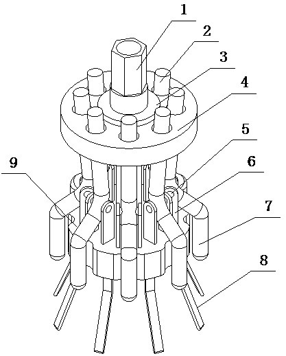
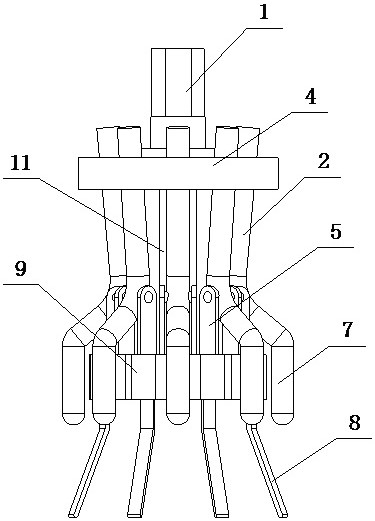
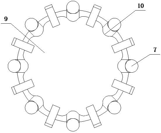
[0020] A steel pipe closing machine of the present invention is realized in the following way: a steel pipe closing machine of the present invention consists of a twisting sleeve (1), a driving rod (2), a supporting sleeve (3), a sliding support sleeve (4), and a hinged shaft ( 5), fixed ear (6), extrusion column (7), centering piece (8), profiling block (9), groove (10) and stud (11), the stud (11) One end is fixed on the profiling block (9), the other end of the stud (11) extends upwards, the sliding brace sleeve (4) is placed on the stud (11), and is close to the stud (11) On the other end, the screwing sleeve (1) is screwed and placed on the other end of the stud (11), the supporting sleeve (3) and the screwing sleeve (1) are fixedly connected, and the supporting sleeve (3) and the sliding brace The sleeves (4) fit together, and there are a plurality of round holes on the sliding block at equal angles, and a plurality of driving rods (2) are inserted into the plurality of ...

Embodiment 2

[0023] The difference between this embodiment and Embodiment 1 is: a spring (12) is sheathed on the stud (11), one end of the spring (12) is connected to the profiling block (9), and the spring ( The other end of 12) is connected with the sliding brace (4), and the sliding brace can slide; when in use, it can support the sliding brace (4) to prevent the sliding brace (4) from sliding down at the beginning to squeeze The rotation of the pressure column (7) affects the normal use of personnel.

Embodiment 3

[0025] The difference between this embodiment and Embodiment 1 is that a screw (14) is screwed on the extruding rod, the screw (14) runs through the extruding rod, and a pressing plate (13) is placed on the screw (14) When in use, personnel can adjust the extension length of the screw (14), and then adjust the extension length of the pressure plate (13), to squeeze the pipe wall, so as to adapt to the closing of stainless steel pipes with different pipe diameters, and have a wide range of applications;

[0026] The connection between the extruding column (7) and the driving rod (2) is designed as an oblique rod, so that the connection between the extruding column (7) and the driving rod (2) is stable and the driving is convenient;

[0027] The other end of the centering piece (8) first extends vertically downwards, and then extends obliquely away from the center line of the sliding brace (4), so that the centering piece (8) is elastic as a whole, and the inner pipe wall is elas...


PUM


Abstract

The invention discloses a steel pipe necking machine, and relates to a necking device which can form a groove to facilitate insertion by means of necking through the extrusion of a profiling clampingblock and extrusion columns and is small in size and convenient to carry. The steel pipe necking machine is characterized in that one end of a stud is fixedly placed on the profiling clamping block; the other end of the stud extends upwards; a sliding supporting sleeve is placed on the stud in a sleeving manner and is close to the other end of the stud; a screwing sleeve is in screwed connection with the other end of the stud; a pressing and supporting sleeve is fixedly connected with the screening sleeve; the pressing and supporting sleeve fits the sliding and supporting sleeve; a plurality of circular holes are formed in a sliding and supporting block at equal angle; a plurality of driving rods are in one-to-one correspondence to the plurality of the circular holes; the other ends of thedriving rods penetrate through the circular holes and extend downwards close to the central line of the sliding and supporting block; a plurality of grooves are formed in the profiling clamping blockat equal angle; a plurality of the extrusion columns are distributed at equal angle along the central line of the profiling clamping block; the extrusion columns are corresponding to the grooves; andthe extrusion columns are correspondingly connected to the driving rods.

Description

technical field [0001] The invention relates to a steel pipe closing machine, which relates to a device for closing stainless steel pipes used in water conservancy projects, and belongs to the field of water conservancy projects. In particular, it relates to a closing device that can form grooves for easy insertion by extruding the closing with a profiling block and an extrusion column, and is small in size and easy to carry and use. Background technique [0002] At present, in water conservancy construction, it is often necessary to connect pipe fittings to each other. However, due to the technological defects in the production and processing of pipe fittings and the mutual extrusion deformation during transportation and handling, there will be certain tolerances in their wall thickness, inner and outer diameters, and ellipticity. , so that the fit is too tight during the plug-in connection, and the plug-in connection cannot be easily performed. However, the existing pipe f...

Claims


Application Information

Patent Timeline
Patent Type & Authority Applications(China)
IPC IPC(8): B21D41/04
CPCB21D41/04
Inventor 不公告发明人
Owner 徐州易尚饰家装饰工程有限责任公司
Why Eureka
Try Eureka