A device for automatically arranging pills
An automatic arrangement and pill technology, applied in packaging and other directions, can solve the problems of slow pill speed, stuffy hands, low benefit, etc., and achieve the effect of saving use
- Summary
- Abstract
- Description
- Claims
- Application Information
AI Technical Summary
Problems solved by technology
Method used
Image

Examples
Embodiment 1
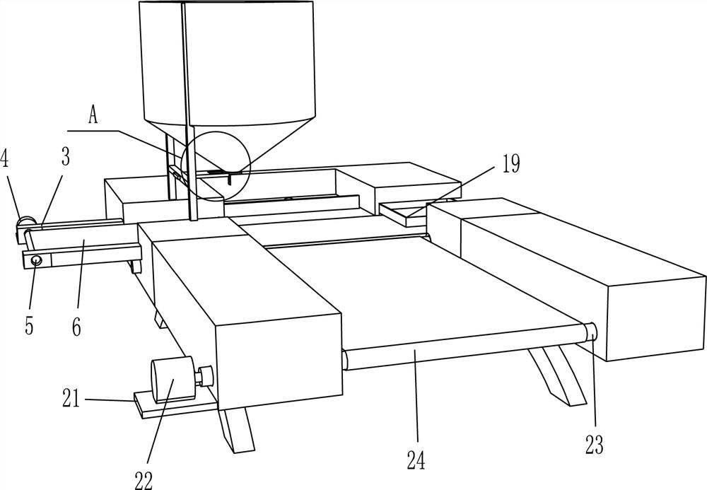
[0054] A pill automatic arrangement device, such as Figure 1-2 As shown, it includes a leg 1, a main board 2, a supporting member 3, a servo motor 4, a circular shaft 5, a conveyor belt 6, a fixing component 7, a drain plate 8, a hydraulic push rod 9, a connecting plate 10, a connecting rod 11, Expansion plate 12, material leakage device, fixed bracket 14, unloading device, push-pull box 19 and electric push rod 20, the two legs 1 are symmetrical, the main board 2 is fixedly connected to the two supporting legs 1, and the main board 2 is provided with a cross The two receiving supports 3 are respectively fixed on the two sides on the left side of the cross groove of the main board 2, and the left parts of the two receiving supports 3 are symmetrically provided with circular through holes, the two receiving supports 3 are symmetrical, and the circular rotating shaft 5 is arranged There are two, wherein one circular rotating shaft 5 passes through the circular through hole of t...
Embodiment 2
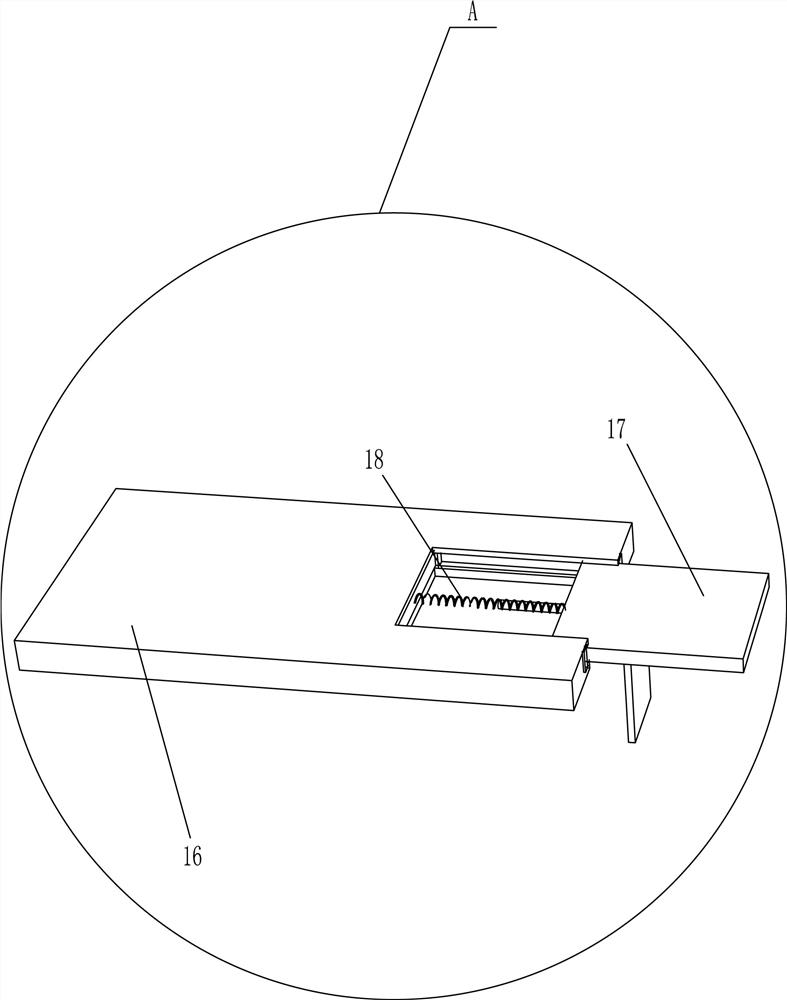
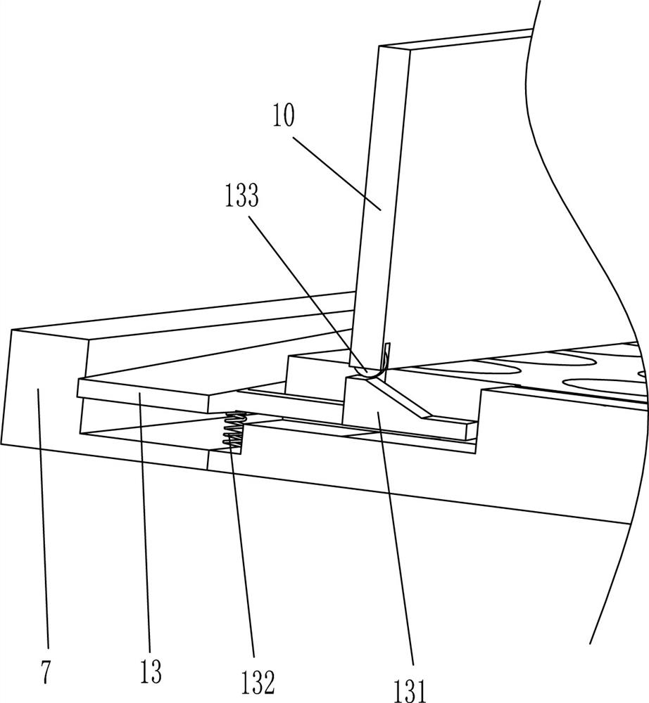
[0057] On the basis of Example 1, such as Figure 1-5As shown, the leaking device includes a swing plate 13, a wedge 131, a return spring 132 and a rolling wheel 133. The bottom of the swing plate 13 is rotatably connected to the right side of the fixed assembly 7, and the wedge 131 is affixed to the top of the swing plate 13. Wedge 131 is located in the drain groove of the bottom wall of fixed component 7, one end of return spring 132 is fixedly connected with fixed component 7, the other end is fixedly connected with swing plate 13 top, and scroll wheel 133 is installed on the rear side of the bottom of connecting plate 10, and scroll wheel 133 is connected with Wedge 131 contacts.
[0058] When the connecting plate 10 moved to the right by the hydraulic pressure push rod 9, the rolling wheel 133 on the connecting plate 10 pressed the wedge 131 and the swing plate 13 downwards, so that the swing plate 13 became an inclined state, and at the same time, the back-moving spring ...
Embodiment 3
[0062] On the basis of Example 2, such as Figure 1-5 As shown, the device for automatically outputting the medicine box is also included, and the device for automatically outputting the medicine box includes an organic base 21, a transmission motor 22, a conveying shaft 23 and a conveyor belt 24, and the base 21 is fixedly connected to the bottom of the left main board 2, and the transmission The motor 22 is installed on the machine base 21, two transmission shafts 23, one transmission shaft 23 is rotatably connected to the second round hole on the lower two walls of the main board 2, and the left end of the transmission shaft 23 is fixedly connected to the output shaft of the transmission motor 22 through a coupling , another conveying shaft 23 is rotatably connected to the third round hole in the middle part of the main board 2, and the conveying belt 24 is wound on the two conveying shafts 23.
[0063] When the push plate of the electric push rod 20 pushes out the pill box...
PUM
 Abstract
Description
Claims
Application Information