Mechanical equipment for concrete pipe gallery construction

A technology of concrete and pipe gallery, applied in artificial islands, water conservancy projects, infrastructure engineering, etc., can solve the problems of high manual labor intensity of steel molds, poor concrete forming quality, and low degree of mechanization, so as to enhance the service life and work Stability, low manufacturing cost, and stable operation

Pending Publication Date: 2020-09-08
ERCHU CO LTD OF CHINA RAILWAY TUNNEL GRP +1
View PDF0 Cites 0 Cited by
  • Summary
  • Abstract
  • Description
  • Claims
  • Application Information

AI Technical Summary

Problems solved by technology

[0003] The purpose of the present invention is to overcome the deficiencies of the prior art and provide a mechanized equipment for the construction of concrete pipe gallery to solve the problem that the wooden formwork and steel formwork used in the construction of pipe

Method used


Image

  • Mechanical equipment for concrete pipe gallery construction
  • Mechanical equipment for concrete pipe gallery construction
  • Mechanical equipment for concrete pipe gallery construction

Examples


Embodiment 1

[0060] A mechanized equipment for the construction of a concrete pipe gallery, comprising: an inner mold formwork part and a lifting trolley part for moving the inner formwork formwork into place.

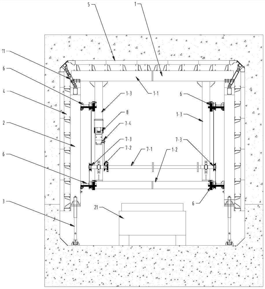
[0061] See attached Figure 1-5 , the mold base part of the internal mold includes a door frame 1, a movable column 2, a column lifting support leg 3, a side template 4, a top template 5, and a translation driver 6, a transmission assembly and a motor 8.

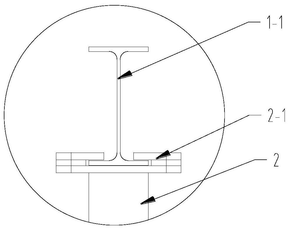
[0062] The door frame 1 is composed of the top door beam 1-1, the bottom cross brace 1-2 and the side vertical brace 1-3. The top door beam is made of H-shaped steel or steel plate tailor-welded into an H shape, and can be bolted by multiple sections. to meet the use of sections with different widths; the side vertical braces 1-3 are fixedly arranged between the top door beam 1-1 and the bottom cross brace 1-2, and play the role of connecting the top door beam and the bottom cross brace. A side vertical brace 1-3 is respectively...

Embodiment 2

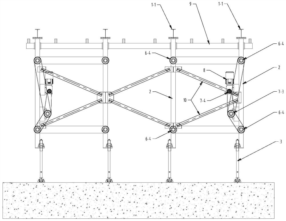
[0078] On the basis of Embodiment 1, further speaking, the inner mold frame can be longitudinally spliced ​​into the required size by a plurality of inner mold frame units to adapt to different construction needs, and each inner mold frame unit can realize a motor 8 at the same time Drive eight translation drivers 6 to act synchronously. Two specific lectures: each internal mold frame unit includes two door frames 1, four movable columns 2, eight translation drivers 6, a motor 8 and a transmission shaft 7-1.

[0079] The two gantry frames are arranged longitudinally at intervals in the front and back, and a movable column is arranged on both sides of each gantry in the transverse direction (width direction). To stabilize the structure and prevent the inner mold formwork unit from being deformed by force, each movable column 2 is connected to the gantry part on its inner side through two translation drivers 6, that is, four translation drivers 6 are installed on each gantry 1; ...

Embodiment 3

[0081] On the basis of Embodiment 1, further, see the accompanying Figure 8 , the specific installation structure of the thrust bearing seat 6-3 and the rotating nut 6-2 of the translation driver 6 is: one end of the rotating nut 6-2 has a flange 6-21; the thrust bearing seat 6-3 includes The upper cover 6-31 and the base 6-32, the upper cover 6-31 and the base 6-32 are butted together by bolts, an installation cavity is formed between the upper cover 6-31 and the base 6-32, and the rotating nut 6- The flange 6-21 of 2 is installed in the installation cavity, and several turns are arranged between the upper surface of the flange 6-21 of the rotating nut 6-2 and the upper cover 6-31 of the thrust bearing seat 6-3. The ball 6-3a, the lower surface of the flange 6-21 of the rotating nut 6-2 and the base 6-32 of the thrust bearing seat 6-3 are also provided with some circles of balls 6-3b, the wing of the rotating nut 6-2 Several rings of balls 6-3c are also arranged between the...


PUM


Abstract

The invention discloses mechanical equipment for concrete pipe gallery construction. The mechanical equipment comprises an inner form formwork and a lifting trolley used for moving the inner form formwork in place, wherein the inner form formwork comprises a portal frame, movable stand columns are arranged on the two sides of the portal frame, side form plates are installed on the movable stand columns, the movable stand columns are connected with the portal frame through translation drivers, a top form plate is mounted at the top of the portal frame, stand column lifting supporting legs are arranged at the bottoms of the movable stand columns, the height of the whole inner form formwork is adjusted through the stand column lifting supporting legs, and a bottom middle supporting leg capable of rising and falling are further arranged at the bottom of the portal frame. During construction, the lifting trolley lifts the inner form formwork to move and be preliminarily in place, the positions of the side form plates and the height of the lifting trolley are adjusted by combining the inner form formwork, and form erecting and form removing work is achieved.

Description

technical field [0001] The invention belongs to the technical field of pipe gallery concrete construction, and in particular relates to mechanized equipment for concrete pipe gallery construction. Background technique [0002] With the rapid development of urbanization, urban land resources are becoming more and more tense, and urban construction projects and public facilities are increasing day by day. Especially in the construction of various pipelines, if the planning and design are improper, repeated excavation will occur. Not only will it affect the normal traffic in the city, but it will also affect the service life of various pipelines. Through the application of comprehensive pipe gallery construction technology, the above problems can be effectively solved and the safe operation of various pipelines can be ensured. The concrete construction of the existing pipe gallery mostly uses wood formwork, steel formwork, etc., which takes a long time to disassemble and assem...

Claims


Application Information

Patent Timeline
IPC IPC(8): E02D29/045
CPCE02D29/10
Inventor 刘伟梁云生刘志成吴相斌董志伟马艳红哈建波刘兴波晋龙凤贾吉春洪开荣毕海柱王秋林申达李晓龙李志军李传江李晓辉董晓亮刘鹏中
Owner ERCHU CO LTD OF CHINA RAILWAY TUNNEL GRP
Why Eureka
Try Eureka