Combined type push-pull tent

A combined and tent technology, applied in the field of tents, can solve the problems of unstable and reliable use of the device, and achieve the effect of diversifying the use of functions.

Inactive Publication Date: 2020-09-08
深圳市贝加尔帐篷有限公司
View PDF5 Cites 2 Cited by
  • Summary
  • Abstract
  • Description
  • Claims
  • Application Information

AI Technical Summary

Problems solved by technology

[0003] When the existing push-pull tent is in use, it is unfolded by pulling. During the pulling process, the moving wheel at the bottom of the tent is in contact with the ground and then slides to ensure that the device pulls more smoothly and makes the pull more labor-saving. However, in actual use , because the moving wheel has no fixed components to fix and limit it, when the device is subjected to strong winds, because the moving wheel has a good lubricating effect, it is more convenient to fold back the tent frame, so that the device is not easy to use Stable and reliable problem, for this the present invention proposes a kind of combined push-pull tent

Method used


Image

  • Combined type push-pull tent
  • Combined type push-pull tent
  • Combined type push-pull tent

Examples


Embodiment 1

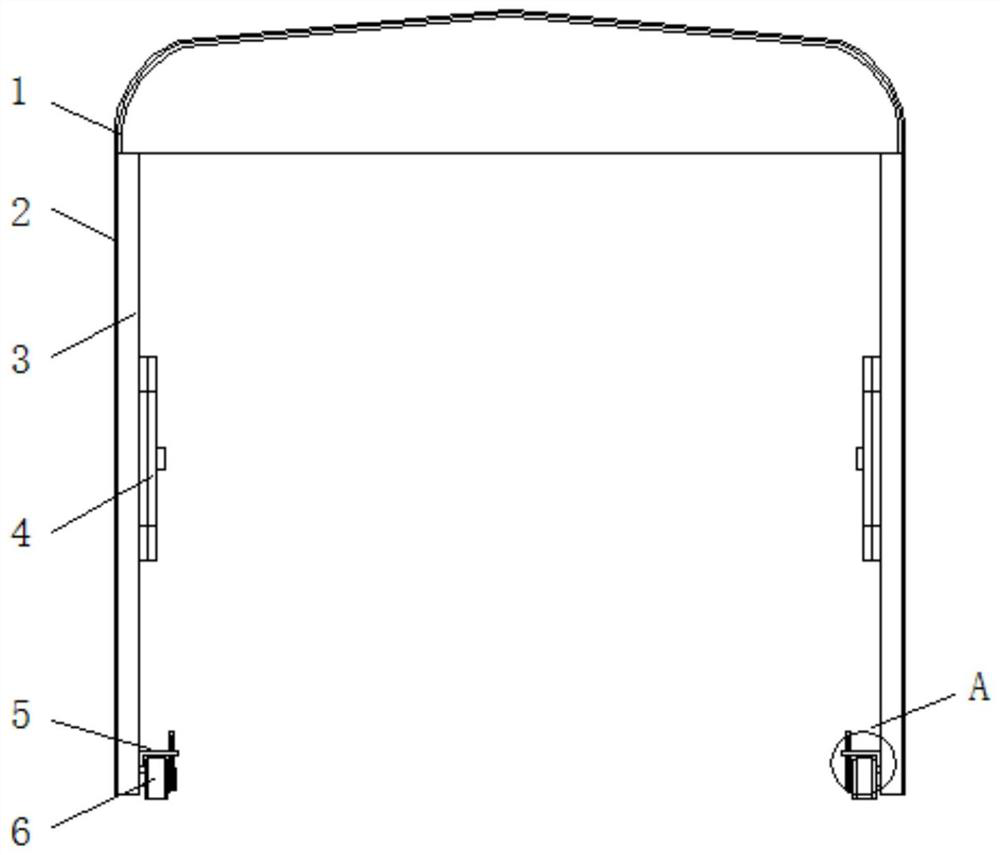
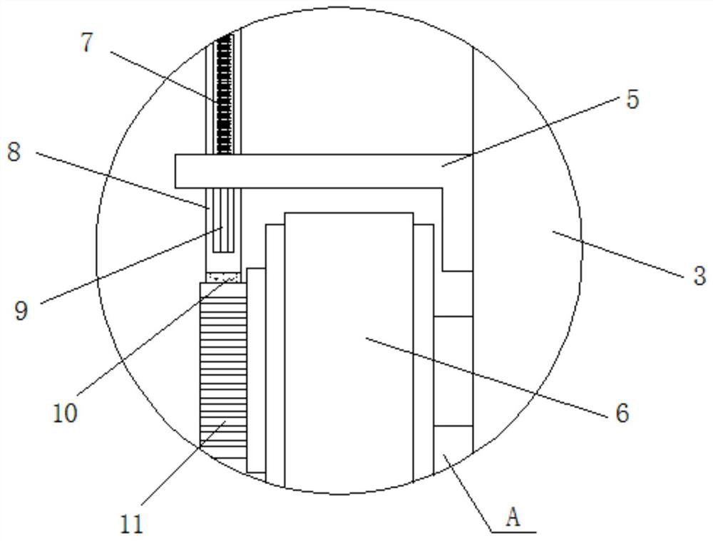
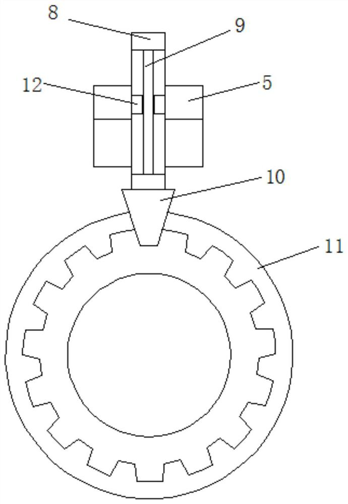
[0024] see Figure 1 to Figure 4 , the present invention provides a technical solution: a combined push-pull tent, including a tarpaulin 2, a tent frame is arranged on the inner side of the tarpaulin 2 in turn, the tent frame is composed of a top frame 1 and a bracket 3, and the bracket 3 is located at both ends of the top frame 1 , the bottom of the bracket 3 is fixed with a moving wheel 6, one end of the moving wheel 6 is fixed with a toothed plate 11, the top of the moving wheel 6 is provided with a mounting frame 5, and one end of the mounting frame 5 runs through a slide bar 8, and the surface of the slide bar 8 is provided with a slide hole. A guide rod 9 is arranged inside the hole, and a baffle plate 12 is set on the outside of the guide rod 9. The baffle plate 12 is fixed inside the installation frame 5, and the bottom of the slide bar 8 is fixed with a magnetic absorption slot 10. Through the designed magnetic absorption slot 10, It is stuck in the toothed disc 11, a...

Embodiment 2

[0027] see Figure 1 to Figure 6 , the present invention provides a technical solution: a combined push-pull tent, including a tarpaulin 2, a tent frame is arranged on the inner side of the tarpaulin 2 in turn, the tent frame is composed of a top frame 1 and a bracket 3, and the bracket 3 is located at both ends of the top frame 1 , the bottom of the bracket 3 is fixed with a moving wheel 6, one end of the moving wheel 6 is fixed with a toothed plate 11, the top of the moving wheel 6 is provided with a mounting frame 5, and one end of the mounting frame 5 runs through a slide bar 8, and the surface of the slide bar 8 is provided with a slide hole. A guide rod 9 is arranged inside the hole, and a baffle plate 12 is set on the outside of the guide rod 9. The baffle plate 12 is fixed inside the installation frame 5, and the bottom of the slide bar 8 is fixed with a magnetic absorption slot 10. Through the designed magnetic absorption slot 10, It is stuck in the toothed disc 11, a...


PUM


Abstract

The invention discloses a combined type push-pull tent. The combined type push-pull tent comprises tent cloth, wherein tent frames are sequentially arranged on the inner side of the tent cloth; each tent frame is composed of a top frame and supports; the supports are positioned at the two ends of the top frame; moving wheels are fixed to the bottoms of the supports; a fluted disc is fixed to one end of each moving wheel; a mounting frame is arranged at the top of each moving wheel; a sliding rod penetrates through one end of each mounting frame; and a sliding hole is formed in the surface of each sliding rod. According to the combined type push-pull tent, designed magnetic attraction groove blocks are clamped in the fluted discs and attract the fluted discs, then the moving wheels are positioned, the moving wheels are not prone to rotating, and the combined type push-pull tent is more stable and reliable in use; and designed springs have good elasticity, then the springs exert the pushing effect on the sliding rods, the magnetic attraction groove blocks are not clamped in the fluted discs, and the moving wheels are not prone to being hindered in the push-pull process of the combined type push-pull tent.

Description

technical field [0001] The invention belongs to the technical field of tents, in particular to a combined push-pull tent. Background technique [0002] When the push-pull tent is in use, the user pulls it horizontally to ensure that the tent frame is unfolded, the tarpaulin is opened, the tent is pulled open, and then placed in a designated position to achieve shelter use. [0003] When the existing push-pull tent is in use, it is unfolded by pulling. During the pulling process, the moving wheels at the bottom of the tent are in contact with the ground and then slide to ensure that the device pulls more smoothly and makes the pull more labor-saving. However, in actual use Because the moving wheel has no fixed components to fix and limit it, when the device is subjected to strong winds, because the moving wheel has a good lubrication effect, it is more convenient to fold back the tent frame, so that the device is not easy to use. Stable and reliable problem, the present inve...

Claims


Application Information

Patent Timeline
IPC IPC(8): E04H15/32E04H15/48A01G25/02F24F5/00
CPCA01G25/02E04H15/32E04H15/48F24F5/00
Inventor 尹良
Owner 深圳市贝加尔帐篷有限公司
Why Eureka
Try Eureka