Manual and pneumatic integrated valve

An integrated valve body technology, applied in fluid pressure actuation devices, servo motor components, mechanical equipment, etc., can solve problems such as increasing leakage points and equipment operation risks.

Inactive Publication Date: 2020-09-08
YINCHUAN INAUTO AUTOMATION
View PDF0 Cites 2 Cited by
  • Summary
  • Abstract
  • Description
  • Claims
  • Application Information

AI Technical Summary

Problems solved by technology

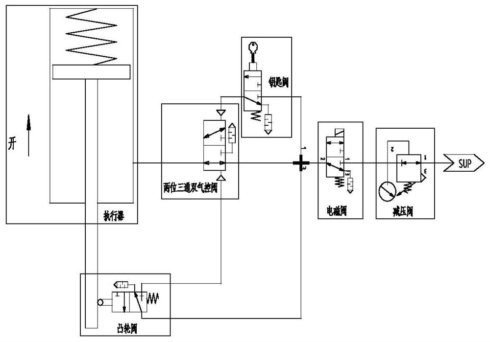
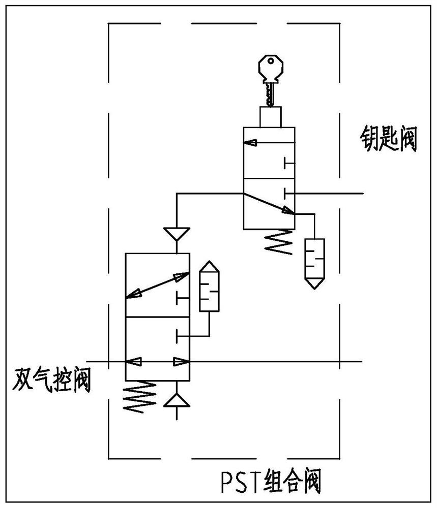
In actual operation, if the button of the two-position three-way manual control valve is pressed all the time, the valve position of the two-position three-way air control valve will not be switched, which will cause the actuator to run to the closed position all the time, which will bring risks to the operation of the equipment. The key valve and the two-way The three-way double air control also needs piping, which virtually increases the leakage point

Method used


Image

  • Manual and pneumatic integrated valve
  • Manual and pneumatic integrated valve
  • Manual and pneumatic integrated valve

Examples


Embodiment Construction

[0017] In order to make the purpose, technical solutions and advantages of the embodiments of the present invention clearer, the technical solutions in the embodiments of the present invention will be clearly and completely described below in conjunction with the drawings in the embodiments of the present invention. Obviously, the described embodiments It is a part of embodiments of the present invention, but not all embodiments. The components of the embodiments of the invention generally described and illustrated in the figures herein may be arranged and designed in a variety of different configurations.

[0018] Accordingly, the following detailed description of the embodiments of the invention provided in the accompanying drawings is not intended to limit the scope of the claimed invention, but merely represents selected embodiments of the invention. Based on the embodiments of the present invention, all other embodiments obtained by persons of ordinary skill in the art wi...


PUM


Abstract

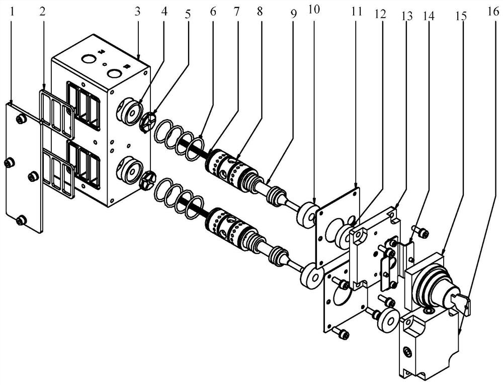
A manual and pneumatic integrated valve comprises a pressing plate, a first sealing gasket, a valve body, a limiting base, a first polyurethane seal ring, an O-ring, a shaft sleeve, a first valve element, a pressing cap, a second sealing gasket, a second polyurethane seal ring, a first upper cover, a button support, a key valve button, a second upper cover and a second valve element. The limitingbase and the first polyurethane seal ring are arranged on the valve body. The O-ring is arranged on the shaft sleeve and used for sealing between the shaft sleeve and the valve body. The valve elementis arranged in the shaft sleeve. A slide valve sealing mode is adopted between the valve element and the shaft sleeve. The pressing cap is arranged at the upper portion of the valve element. The second polyurethane seal ring is arranged in the first upper cover. The button support is arranged on the first upper cover. The second sealing gasket and the first upper cover are assembled together andarranged in the valve body. The key valve button is arranged on the second upper cover. The second upper cover is arranged on the valve body. The manual and pneumatic integrated valve has functions ofa key valve, also has functions of a two-position three-way double-air-control valve and can make a PST partial stroke test loop simpler and more reliable.

Description

Technical field: [0001] The invention relates to a pneumatic valve used in a pneumatic circuit, in particular to a manual pneumatic integrated valve used in a pneumatic circuit for PST partial stroke testing. The manual pneumatic integrated valve is used for PST partial stroke testing of an ESD valve controlled by a pneumatic actuator. Background technique: [0002] The so-called partial stroke test (PST-Partial Stroke Test) of the ESD valve is used as a safety measure for the ESD-Emergency Shutdown valve. The method of detecting faults in the ESD valve system is to let the ESD valve do periodic part of the stroke action. For example: ESD valve partially closes 10-30% of the stroke from the fully open position, and sets periodic actions according to a certain time interval, so as to better check the movement of the valve stem and judge whether the working status of its function is normal. PST is a reliable detection method that does not affect the normal operation of ESD va...

Claims


Application Information

Patent Timeline
Patent Type & Authority Applications(China)
IPC IPC(8): F15B13/02F15B13/04
CPCF15B13/02F15B13/04
Inventor 赫天生余凯安润仓王新标
Owner YINCHUAN INAUTO AUTOMATION
Why Eureka
Try Eureka