Deflection compensation type multi-spindle machining center

A machining center and spindle machining technology, applied in the direction of manufacturing tools, other manufacturing equipment/tools, etc., can solve problems such as workpiece machining deviation, achieve the effect of ensuring machining accuracy and overcoming thermal deformation

Inactive Publication Date: 2020-09-11
杭州友佳精密机械有限公司
View PDF9 Cites 0 Cited by
  • Summary
  • Abstract
  • Description
  • Claims
  • Application Information

AI Technical Summary

Problems solved by technology

However, when processing multiple processing points, due to thermal deformation and other factors, the position on each plane of the workpiece may be slightly displaced, and the relative position of each processing point may also change. Causes deviations in final workpiece machining

Method used


Image

  • Deflection compensation type multi-spindle machining center
  • Deflection compensation type multi-spindle machining center
  • Deflection compensation type multi-spindle machining center

Examples


Embodiment 1

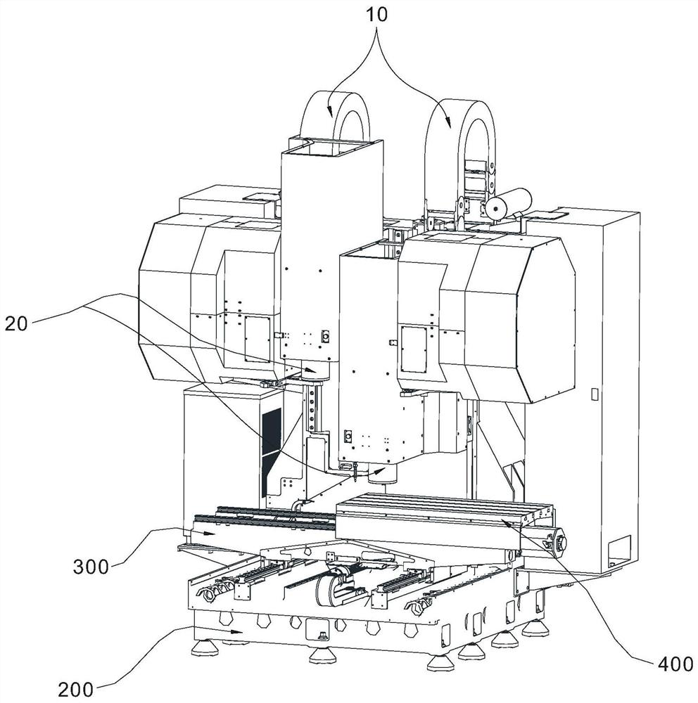
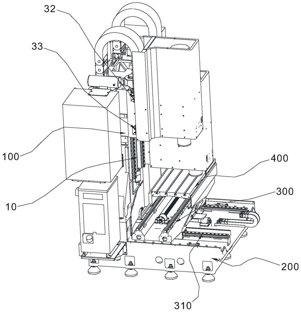
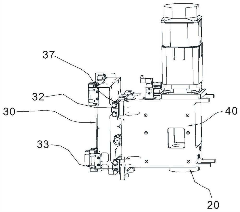
[0023] like Figure 1 to Figure 5 As shown, a displacement compensation multi-spindle machining center includes a main base 200, a main column 100, a saddle 300, a worktable 400, two spindle processing units, and a workpiece pallet exchange mechanism. The main column 100 is fixed on the main base 200 and is perpendicular to the ground, and a honeycomb lattice structure is arranged inside the main column 100 . The spindle processing unit is slidably connected to the main column 100, the saddle 300 is slidably connected to the main base 200, the Y-axis driving mechanism 310 is connected between the saddle 300 and the main base 200, the workbench 400 is slidably connected to the saddle 300, and the saddle 300 is slidably connected to the main base 200. The seat 300 is connected to the Y-axis driving mechanism 310 , and the X-axis driving mechanism is connected between the workbench 400 and the saddle 300 . The spindle processing unit includes a spindle 20 , an X-axis displacemen...

Embodiment 2

[0026] There are three spindle processing units. All the other are with embodiment 1.

Embodiment 3

[0028] There are four spindle processing units. All the other are with embodiment 1.


PUM


Abstract

The invention discloses a displacement compensation type multi-spindle machining center. The displacement compensation type multi-spindle machining center comprises a main base, a main stand column, asaddle, a workbench and at least two spindle machining units, the stand column is fixed to the main base, the spindle machining units are connected to the stand column in a sliding mode, and a Z-axisdriving device is arranged between the spindle machining units and the stand column. The main shaft machining unit comprises a main shaft and a unit body, the main shaft is installed on the unit body, an X-axis direction displacement compensation mechanism is arranged between the main shaft machining unit and the main stand column and comprises a unit base plate, a guide rail and a motor, the guide rail is arranged on the unit base plate, and the unit body is connected to the guide rail in a sliding mode, and a transmission mechanism is connected between the motor and the unit main body. Micro-motion compensation can be carried out on fine deflection of all machining points on the workpiece in the X-axis direction.

Description

technical field [0001] The invention relates to a numerical control machining equipment, more specifically, it relates to a displacement compensation type multi-spindle machining center. Background technique [0002] The working method of a conventional machining center is that the saddle and the table move up and down in the X-axis direction and in the front-back direction in the Y-axis direction to set the position of the workpiece on the table on the horizontal plane, and the spindle processing unit moves up and down in the Z-axis direction. Move, and process structures such as surfaces, grooves, and holes through the rotating spindle. In order to improve processing efficiency, some machining center manufacturers have introduced multi-spindle machining centers with multiple spindles that can simultaneously process multiple processing points on the same workpiece. However, when processing multiple processing points, due to thermal deformation and other factors, the positi...

Claims


Application Information

Patent Timeline
IPC IPC(8): B23Q23/00
CPCB23Q23/00
Inventor 周雄强张梁李钻
Owner 杭州友佳精密机械有限公司
Why Eureka
Try Eureka