

Escape device and underwater robot
A technology of mounting plate and accommodating space, applied in underwater operation equipment, manipulator, transportation and packaging, etc., can solve problems such as difficulty in getting out of trouble, and achieve the effect of improving the ability to get out of trouble
- Summary
- Abstract
- Description
- Claims
- Application Information
AI Technical Summary
Problems solved by technology
Method used
Image

Examples
Embodiment 1
[0028] The technical problem to be solved in this embodiment is that the front end of the crawler belt 10 of the existing underwater robot is easy to sink into the mud, and the continuous rotation of the engine causes the crawler belt 10 to sink deeper and deeper in the mud, making it difficult to escape.
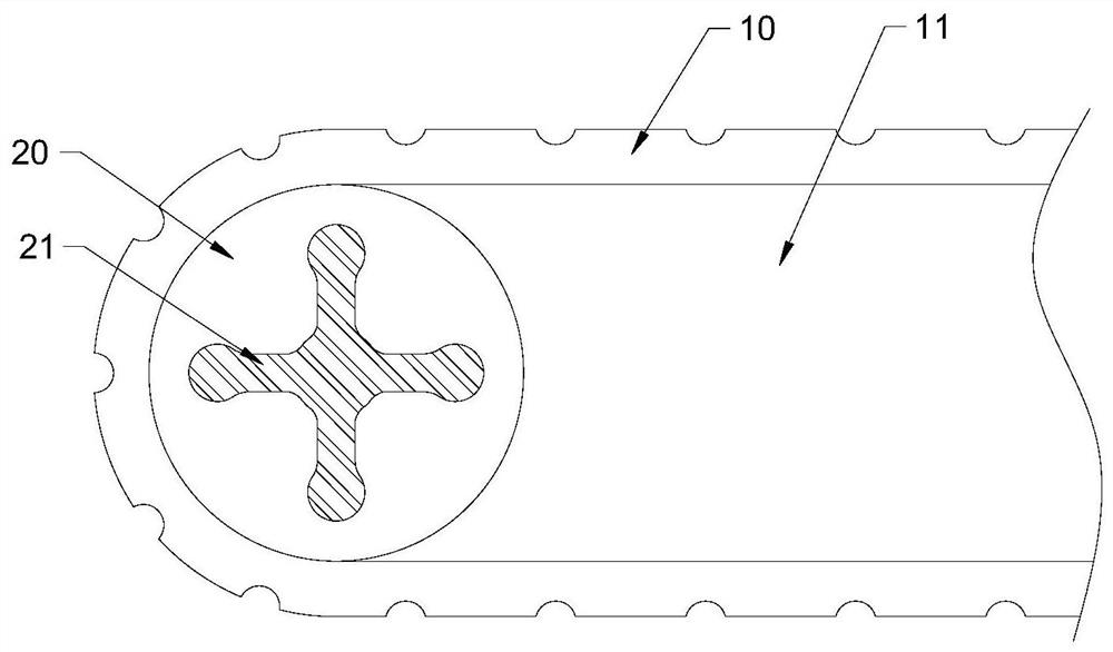
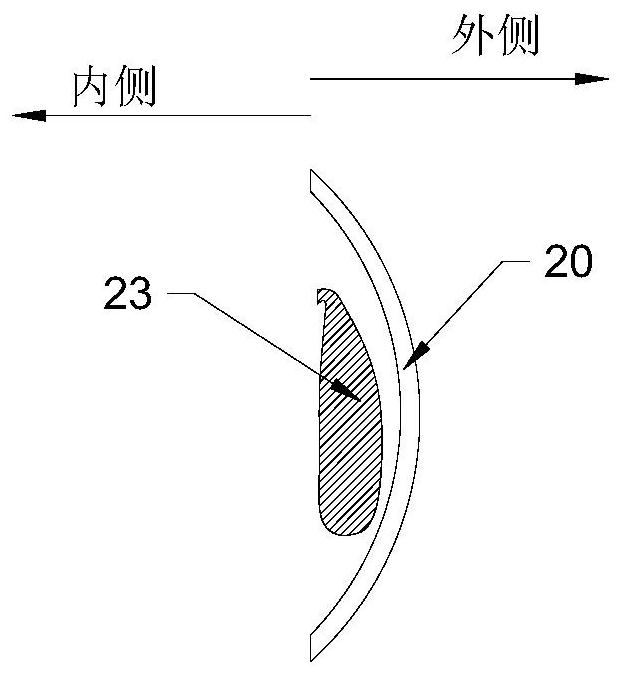
[0029] In order to solve the above-mentioned technical problems, this embodiment provides a device for getting out of trouble, such as Figure 1-2 Shown, comprise the escape disc 20 and air bag 23. The escape plate 20 is a disc-shaped component made of metal, and the air bag 23 is a thick-walled bag that can be inflated and deflated.
[0030] The trapping disc 20 is arranged on the driving shaft 12 outside the buoyancy tank 11 , and the trapping disc 20 rotates with the driving shaft 12 . The driving shaft 12 protrudes from the outside of the buoyancy tank 11 , and the escape disc 20 is arranged on the protruding end of the driving shaft 12 .
[0031] The trapping plate 2...
Embodiment 2
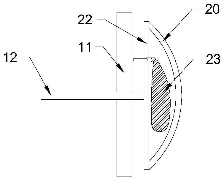
[0036] This embodiment provides a trapping device, including a trapping plate 20 , a mounting plate 22 and an airbag 23 .
[0037] The trapping disc 20 is arranged on the drive shaft 12 outside the buoyancy tank 11, and the installation disc 22 is also arranged on the drive shaft 12 outside the buoyancy tank 11, and the trapping disc 20 and the mounting disc 22 rotate with the drive shaft 12; An accommodating space is formed between the escape plate 20 and the mounting plate 22, and the air bag 23 is disposed in the accommodating space.
[0038] The control assembly of the airbag 23 is arranged between the mounting plate 22 and the buoyancy tank 11, and the control assembly includes an inflation solenoid valve; when the inflation solenoid valve receives an inflation signal, it fills the airbag 23 with a set amount of gas.
[0039] The control assembly also includes a deflation solenoid valve, a compressor and an air storage tank; when the deflation solenoid valve receives a de...
Embodiment 3
[0045] A device for getting out of trouble, comprising a trapping disc 20 and an air bag 23, the disc 20 for getting out of trouble is arranged on the drive shaft 12 outside the buoyancy tank 11, the disc 20 for getting out of trouble rotates with the drive shaft 12; the disc 20 for getting out of trouble has an outward convex The raised outer wall of the convex surface, the air bag 23 is arranged between the escape plate 20 and the buoyancy tank 11, and an opening 21 is also arranged on the outer wall of the convex surface; when the air bag 23 expands, the capsule body of the air bag 23 fills the escape plate 20 inside and protrudes outward from the opening 21 of the convex outer wall.
[0046] The escape disc 20 includes two half-disks, which are fixedly connected by a plurality of connecting straps, and when the airbag 23 expands to the maximum, the airbag 23 breaks the connecting straps and makes the two half-discs Disc separation.
[0047] In this embodiment, when the ai...
PUM
 Abstract
Description
Claims
Application Information