Switch machine point rail position monitoring system with redundant configuration and switch machine

A technology of redundant configuration and monitoring system, applied in the direction of locking mechanism for turnout, electrical equipment for operating turnout or line interrupter, railway signal, etc. Column blocking and other problems, to achieve the effect of simple circuit design, reduction of manual maintenance, and avoidance of misoperation

Pending Publication Date: 2020-09-11
ZHEJIANG UNIV +1
View PDF6 Cites 4 Cited by
  • Summary
  • Abstract
  • Description
  • Claims
  • Application Information

AI Technical Summary

Problems solved by technology

[0002] The current switch machine includes power unit, transmission mechanism, locking device, and display device (automatic switch and switch display circuit). The switch machine can only be controlled centrally through interlocking equipment. The further development of the current point machine cannot realize the autonomous control of the train, and the current point machine turnout circuit can only realize the rotation control of the turnout motor and the circuit representation of its own state, and cannot analyze and report its own operating state and fail. predict
The automatic switch mechanism is relatively ingenious and complex, and is greatly affected by the internal environment of the switch machine box. With the increase of the number of actions, the spring force will gradually weaken, and the wear rate will also be significantly accelerated; and its internal components are not easy. Cleaning, after working for a long time, the inspection column is easily wrapped by oil, dust, etc., resulting in inflexible falling, and the inspection column is jammed in the action hole
These situations will have a great impact on the reliability of the switch machine position representation module

Method used


Image

  • Switch machine point rail position monitoring system with redundant configuration and switch machine
  • Switch machine point rail position monitoring system with redundant configuration and switch machine
  • Switch machine point rail position monitoring system with redundant configuration and switch machine

Examples


Embodiment 1

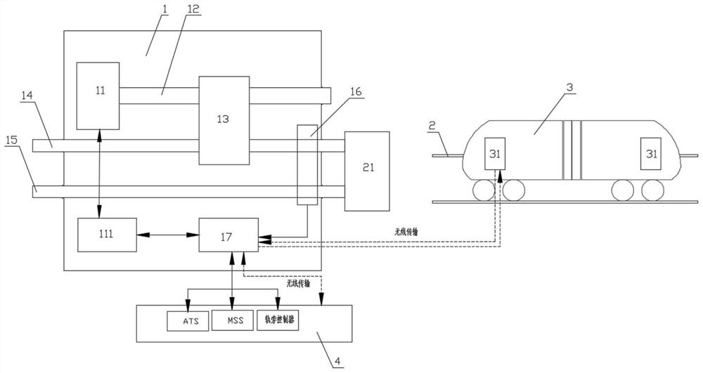
[0031] refer to Figure 1 to Figure 4 As shown, an intelligent switch machine 1 that can be independently controlled by the train. The train runs on the track 2. The switch machine 1 controls the point rail 21 of the switch to change the position of the switch. Remotely control the switch machine 1. It includes a switch machine driving device, a switch machine position indicating device, a sensor group 16 and a core processing board 17 . The switch machine driving device includes a motor 11, a transmission mechanism 12, and an action lever 14. The motor 11 drives the action lever 14 through the transmission mechanism 12, and the action lever 14 drives the switch point rail 21 to move.

[0032] Wherein, the switch machine position display device includes a display rod 15 and a display rod monitoring sensor, the display rod 15 is connected with the switch switch rail 21, and the action rod 14 pushes the switch switch rail 21 to move, and then the display rod 15 moves along with...

Embodiment 2

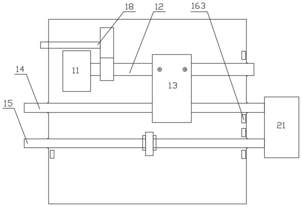
[0048] If the switch machine 1 breaks down, the motor 11 cannot drive the action lever 14 to reset. Such as figure 2 As shown, the switch machine 1 is provided with a gear mechanism 18, the gear mechanism 18 is connected with the self-locking transmission mechanism, and the gear mechanism 18 is connected with the handle, so that when the switch machine 1 breaks down, the action rod 14 can be manually reset by shaking the handle. .

Embodiment 3

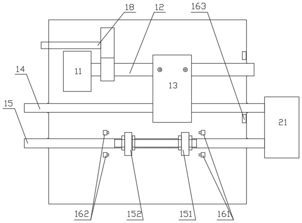
[0050] Such as image 3 As shown, in this embodiment, the indicator rod monitoring sensor is a travel switch, the positive position locking member 151 and the reverse position locking member 152 are installed on the indicating rod 15, and the corresponding normal position locking The piece 151 is provided with a positive position travel switch 161 , and the corresponding reverse position locking piece 152 is provided with a reverse position travel switch 162 . The normal position locking member 151 is used to trigger the normal position travel switch 161 of the indicating rod to monitor the normal position of the indicating rod 15 . The reverse position locking member 152 is used to trigger the reverse travel switch 162 of the indicator rod to monitor the reverse position of the indicator rod 15 .

[0051] Optionally, there are two forward travel switches 161 which are mutually redundant, and two reverse travel switches 162 are also provided with two mutually redundant.

[0...


PUM


Abstract

The invention discloses a switch machine point rail position monitoring system with redundant configuration and a switch machine. The switch machine drives an actuating rod through a motor, the actuating rod drives a turnout point rail to act, and a switch machine position indicating device comprises an indicating rod moving along with the action of the turnout point rail and an indicating rod monitoring sensor used for monitoring the position of the indicating rod so as to monitor the current position of the turnout switch rail. In view of the defects of an automatic opening and closing device mechanism of an existing switch machine, position indication of the switch machine adopts an indicating rod moving along with a turnout switch rail and an indicating rod monitoring sensor for monitoring the indicating rod, an existing automatic opening and closing mechanism is replaced, the structure is simplified, close indication can be adjusted in a self-adaptive mode according to motor driving torque and indicating rod position information, and manual maintenance is reduced.

Description

technical field [0001] The invention belongs to the technical field of intelligent transportation, and in particular relates to switch machine technology. Background technique [0002] The current switch machine includes power unit, transmission mechanism, locking device, and display device (automatic switch and switch display circuit). The switch machine can only be controlled centrally through interlocking equipment. The further development of the current point machine cannot realize the autonomous control of the train, and the current point machine turnout circuit can only realize the rotation control of the turnout motor and the circuit representation of its own state, and cannot analyze and report its own operating state and fail. predict. The automatic switch mechanism is relatively ingenious and complex, and is greatly affected by the internal environment of the switch machine box. With the increase of the number of actions, the spring force will gradually weaken, an...

Claims


Application Information

Patent Timeline
Patent Type & Authority Applications(China)
IPC IPC(8): B61L5/10B61L5/06
CPCB61L5/102B61L5/065
Inventor 刘丹丹陈祥献凌祝军
Owner ZHEJIANG UNIV
Why Eureka
Try Eureka