
Embedded electric drive course stability augmentation type skid landing device and working method thereof

A landing device, electric drive technology, applied in the direction of sleds/sleds, etc., can solve the problems of uncompact mechanism, poor heading stability, unstable direction, etc., and achieve the effect of preventing the aircraft from drifting and enhancing the heading stability.

Pending Publication Date: 2020-09-11
NANJING UNIV OF AERONAUTICS & ASTRONAUTICS
View PDF0 Cites 3 Cited by
  • Summary
  • Abstract
  • Description
  • Claims
  • Application Information

AI Technical Summary

Problems solved by technology

However, for hypersonic vehicles that use skid landing gear to land, the traditional skid landing gear has problems such as unstable directions. Some of the patents for skid landing gear that have been published so far also have problems such as uncompact mechanisms, Poor heading stability and other problems, and most of them rely on the hydraulic system for actuation. Compared with the all-electric landing gear system that replaces the hydraulic system with an electric system, it has advantages in many aspects. The all-electric heading stability-enhancing skid landing device has greater research value

Method used


Image

  • Embedded electric drive course stability augmentation type skid landing device and working method thereof
  • Embedded electric drive course stability augmentation type skid landing device and working method thereof
  • Embedded electric drive course stability augmentation type skid landing device and working method thereof

Examples


Embodiment Construction

[0043] The technical solutions in the embodiments of the present invention will be clearly and completely described below in conjunction with the accompanying drawings in the embodiments of the present invention. Obviously, the described embodiments are only some of the embodiments of the present invention, not all of them; based on The embodiments of the present invention and all other embodiments obtained by persons of ordinary skill in the art without making creative efforts belong to the protection scope of the present invention.

[0044] It should be noted that the words "front", "rear", "left", "right", "upper" and "lower" used in the following description refer to the directions in the drawings, and the words "inner" and "outer ” refer to directions towards or away from the geometric center of a particular part, respectively.

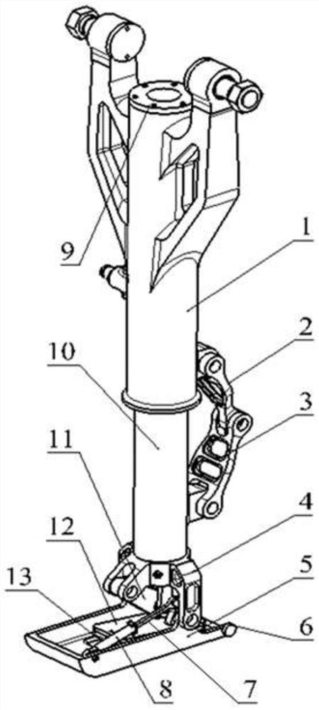
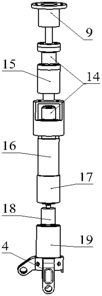
[0045] A skid landing device with built-in electric drive course stability enhancement, including an outer cylinder 1, an upper torque arm 2, a ...


PUM


Abstract

The invention discloses an embedded electric drive course stability augmentation type skid landing device and a working method thereof. The embedded electric drive course stability augmentation type skid landing device comprises an outer cylinder, an upper torsion arm, a lower torsion arm, a support, a skid, a guide wheel, an upper end cover, a piston rod, a rocker arm, a mounting plate, a friction plate, a load sensor, a buffer, a skid pitching buffer and an actuator cylinder module. The invention particularly provides an embedded electric drive course stability augmentation type skid landingdevice and a working method thereof. When the aircraft deviates in the sliding direction, the system controls the brushless motor to drive the rocker arm connecting rod mechanism to press the friction plate down the road surface to generate pressure, therefore, the binding force between the single-side landing device and the road surface is changed, the fuselage is subjected to yawing moment, sothat the skating direction of the aircraft is corrected, and the skating course stability of the aircraft is enhanced; the load sensor can measure the pressure of the friction plate on the road surface and provide feedback, the friction plate is made of a heat-resistant composite material, and specific lines are machined at the bottom of the friction plate, so that extra lateral force is provided,and the drifting phenomenon of the aircraft is reduced.

Description

technical field [0001] The invention relates to the technical field of hypersonic aircraft taxiing and landing, in particular to a skid landing device with built-in electric drive course stabilization and a working method thereof. Background technique [0002] Landing gear is mainly divided into wheeled landing gear and skid landing gear. Traditional aircraft mostly use wheeled landing gear, which is stable and easy to roll when landing, but there are problems such as complex structure, heavy weight, and large space occupation. The skid landing gear has the advantages of simple structure, light weight, low cost, reliable performance and small space occupation. For some hypersonic models, in order to reduce the design limitations of the landing gear on the retractable space and structural weight, a skid-type landing device is also used to decelerate and brake through the friction between the skid and the road surface. The X-15A of the United States used skid landing and cond...

Claims


Application Information

Patent Timeline
Patent Type & Authority Applications(China)
IPC IPC(8): B64C25/52
CPCB64C25/52
Inventor 印寅房务官王宇晟陈平聂宏魏小辉梁涛涛
Owner NANJING UNIV OF AERONAUTICS & ASTRONAUTICS
Learn More