Emergency treatment device and treatment method for urban flood control

An emergency treatment and urban technology, applied in water supply devices, cleaning methods, waterway systems, etc., can solve problems that affect people's work and life, casualties, and slow progress in the development of emergency treatment equipment

Inactive Publication Date: 2020-09-11
李海波
View PDF7 Cites 1 Cited by
  • Summary
  • Abstract
  • Description
  • Claims
  • Application Information

AI Technical Summary

Problems solved by technology

In recent years, due to the rapid development of cities, the unbalanced drainage pipe network system in old and new urban areas, different altitudes, and different rainfall in some areas, some areas have strong drainage capacity and will not form waterlogging, and some areas have serious water accumulation. The formation of waterlogging seriously affects people's work and life, and even causes casualties and huge losses
[0004] However, due to the complex terrain in the city and the long period of time for large-scale reconstruction of the pipe network, drainage is usually pumped between the pipe networks, and the accumulated water in the pipe network with a large load is drained into the pipe network with a small load to form a multi-area drainage system. Flood balance, such a common pipe network that cooperates with each other to pump and drain water is a first-level flood control measure, but it is still difficult to take care of low-lying areas in many cities. Now many people are developing a method that is independent of the first-level flood control measures. Real-time installation and use of emergency treatment equipment with quick results is expected to reduce the loss of flood disasters as much as possible before the complete transformation of the pipeline network. It simply accelerates the ground water to be pumped into the pipe network, and it does not have much effect when the drainage capacity of the pipe network is limited.

Method used


Image

  • Emergency treatment device and treatment method for urban flood control
  • Emergency treatment device and treatment method for urban flood control

Examples


Embodiment 1

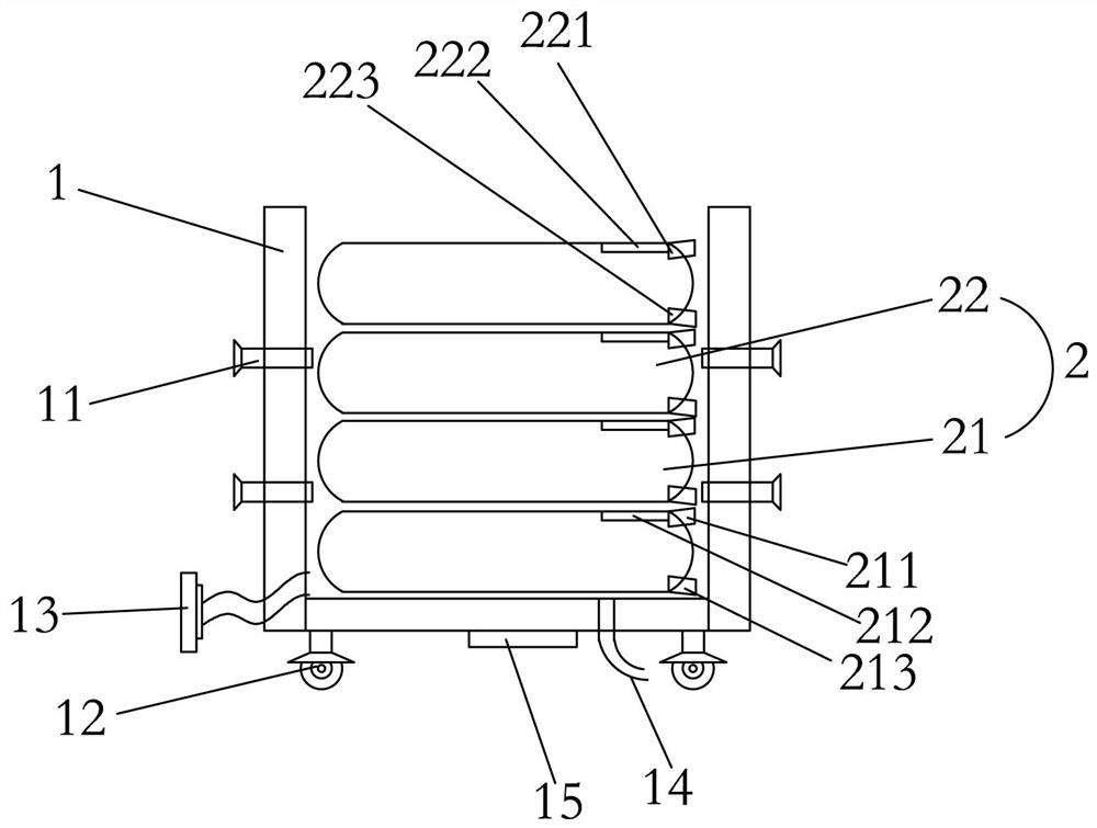
[0042] Example one: such as figure 1 As shown, which is only one of the embodiments of the present invention, an urban flood control emergency treatment device includes a frame 1 and a water storage cavity 2 arranged in the frame 1, and the frame 1 is provided with Supporting the fixed column 11 of the frame 1, the water storage cavity 2 includes a first water storage cavity 21 arranged below and a second water storage cavity 22 arranged above, and the first water storage cavity 21 is arranged There are a first water inlet 211, a first sensor 212, and a first drain 213. The second water storage cavity 22 is provided with a second water inlet 221, a second sensor 222 and a second drain 223. The frame 1 is provided with a total water inlet 13, a total water outlet 14 and a water accumulation sensor 15.

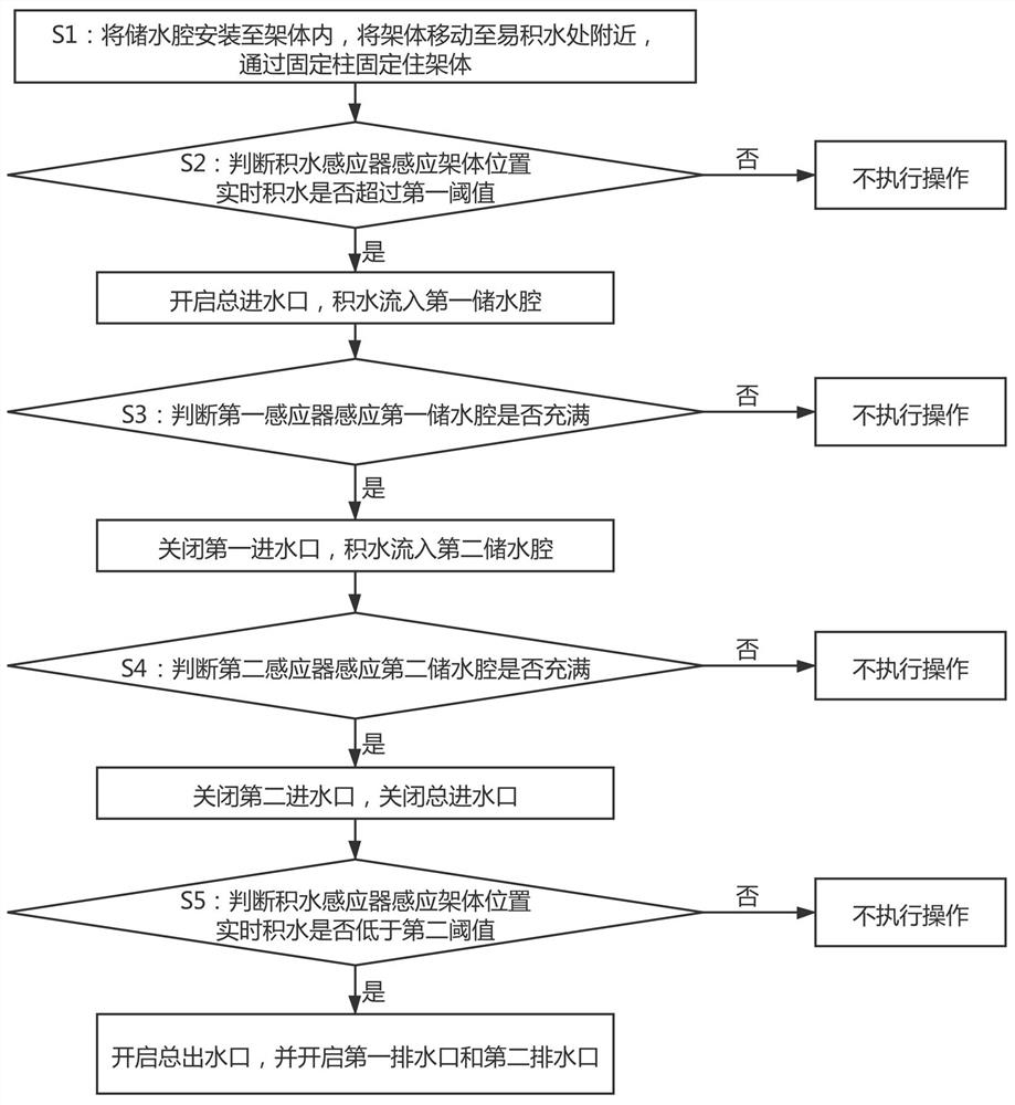
[0043] Before use, the frame 1 is generally set near the place where water is easy to accumulate in the city, and the water storage cavity 2 is laid on the frame 1. The position of...

Embodiment 2

[0050] Example two, still as figure 1 As shown, it is still one of the embodiments of the present invention. In order to facilitate water storage and drainage, the present invention also has the following design: the water storage cavity 2 is arranged in multiple layers, and the second water storage cavity 22 is arranged in the first water storage cavity 21 on the side.

[0051] The number of the first water storage cavity 21 is at least one. In fact, the first water storage cavity 21 is provided with at least one layer, and the first water storage cavity 21 is a canvas capsule to prevent it from being pierced by sharp objects If water leaks, the first water storage cavity 21 can support at least 10 meters high water pressure. Generally speaking, the first water storage cavity 21 is provided with two layers.

[0052] Similarly, the number of the second water storage cavity 22 is at least one, and the same, the second water storage 22 is provided with at least one layer, and the se...

Embodiment 3

[0057] Example three, still as figure 1 As shown, it is still one of the embodiments of the present invention. The difference from the second embodiment is that the present invention can also be directly placed in an open urban area for drainage. At this time, the water storage cavity 2 can be flattened on the ground. The number of water storage chambers needs to be determined. The water storage chamber 2 has only one layer, but each layer can have multiple rows, and each row can also have multiple rows.

[0058] At this time, the total water inlet 13 is connected to the municipal drainage pipe through a water pump, and the water is directly pumped from the municipal drainage pipe through the pump and filled into the water storage cavity 2, alleviating the lack of municipal drainage capacity. After the flood season, the total water outlet 13 is opened, and the accumulated water in each water storage cavity 2 is discharged sequentially.

[0059] It should be noted that each water st...


PUM


Abstract

The invention provides an emergency treatment device and treatment method for urban flood control and relates to the technical field of urban flood control. The emergency treatment device comprises arack body and a water storage cavity. A fixed column is arranged on the rack body. The water storage cavity comprises a first water storage cavity and a second water storage cavity. A first water inlet, a first inductor and a first drainage outlet are formed in the first water storage cavity. A second water inlet, a second inductor and a second drainage outlet are formed in the second water storage cavity. A general water inlet, a general water outlet and an accumulated water inductor are arranged on the rack body. The emergency treatment device and treatment method for urban flood control provided by the invention are simple in structure, convenient to assemble and high in flexibility. The emergency treatment device mounted at an urban place easy to accumulate water can store and collectrainwater effectively during rainfall and then drains the rainwater into a municipal pipe network after rainfall. The emergency treatment device is independent from the drainage pipe network and is not limited by the drainage capacity of the drainage pipe network, so that the urban flood control loss is reduced effectively.

Description

Technical field [0001] The invention relates to the technical field of urban flood control, [0002] In particular, the present invention relates to an emergency treatment device and method for urban flood control. Background technique [0003] Building cities with digital disaster early warning capabilities and intelligent disaster prevention capabilities is a new concept of intelligent cities based on big data platforms in my country, and it is also a new trend in future urban development. In recent years, due to the rapid development of the city, the imbalance of the drainage pipe network system in the old and new urban areas, the different altitudes of the regions, and the difference in rainfall, etc., have led to strong drainage capacity in some areas without the formation of internal waterlogging and water accumulation in some areas. The formation of waterlogging has seriously affected people's work and life, and even caused casualties and huge losses. [0004] However, due t...

Claims


Application Information

Patent Timeline
Patent Type & Authority Applications(China)
IPC IPC(8): E03F5/10E01H1/10
CPCE01H1/108E03F5/10
Inventor 李海波李泽诚
Owner 李海波
Why Eureka
Try Eureka