
Double-cylinder floating breakwater auxiliary power generation device

A floating breakwater and power generation device technology, which is applied in the direction of breakwaters, hydroelectric power generation, ocean energy power generation, etc., can solve the problems of high maintenance costs, low power generation efficiency, and high cost, and achieve low manufacturing costs, high power generation efficiency, and improved power generation efficiency Effect

Active Publication Date: 2020-09-11
HOHAI UNIV
View PDF10 Cites 1 Cited by
  • Summary
  • Abstract
  • Description
  • Claims
  • Application Information

AI Technical Summary

Problems solved by technology

At present, breakwater power generation is mainly divided into three types: the first type is the pendulum plate type, and the wave drives the pendulum plate placed on the breakwater to generate electricity. This pendulum plate structure requires a relatively large space and relatively high maintenance costs; the second type It is a wave-surpassing power generation. The principle of power generation is to build a high-water reservoir behind the embankment. The waves that cross over enter the reservoir and flow into the sea to drive turbines to generate electricity. However, this structure requires the construction of reservoirs and equipment for generating turbines, and the cost is relatively high; the third type It is an oscillating water column type. Its principle is to squeeze the air through the change of water level, thereby driving the air pressure rotor to generate power. It is a three-stage conversion structure with low power generation efficiency.

Method used


Image

  • Double-cylinder floating breakwater auxiliary power generation device
  • Double-cylinder floating breakwater auxiliary power generation device
  • Double-cylinder floating breakwater auxiliary power generation device

Examples


Embodiment Construction

[0031] The present invention will be further described below in conjunction with the accompanying drawings. The following examples are only used to illustrate the technical solution of the present invention more clearly, but not to limit the protection scope of the present invention.

[0032] It should be noted that, in the description of the present invention, the terms "front", "rear", "left", "right", "upper", "lower", "inner", "outer" and the like indicate orientations or positions The relationship is based on the orientation or positional relationship shown in the drawings, and is only for the convenience of describing the present invention and does not require that the present invention must be constructed and operated in a specific orientation, and thus should not be construed as a limitation of the present invention.

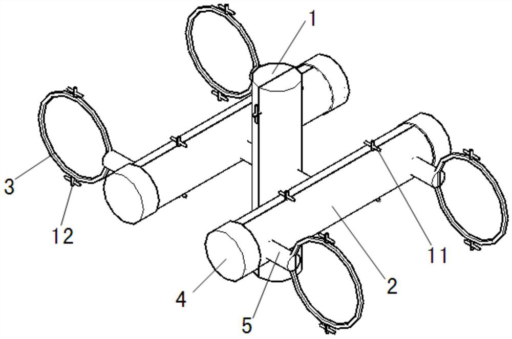
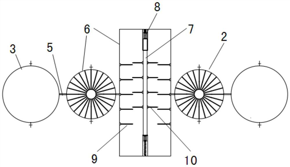
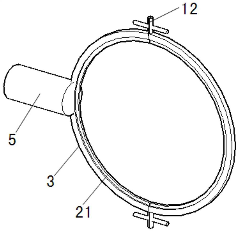
[0033] like figure 1 and 2 As shown, a power generation device attached to a double-barrel floating breakwater includes a vertical power generation cy...


PUM


Abstract

The invention discloses a double-cylinder floating breakwater auxiliary power generation device. The device comprises a vertical power generation cylinder, horizontal power generation cylinders vertically connected with the two sides of the vertical power generation cylinder and a plurality of fixing assemblies connected with the horizontal power generation cylinders. The vertical power generationcylinder and the horizontal power generation cylinders are of the same structure and each comprise an outer cylinder, an inner cylinder arranged in the outer cylinder and a buffer assembly connectedwith the two ends of the outer cylinder and the two ends of the inner cylinder; a plurality of inner shifting pieces are arranged on the inner wall of the outer cylinder, a plurality of outer shiftingpieces are arranged on the outer wall of the inner cylinder, and piezoelectric vibrators are arranged on the inner shifting pieces and the outer shifting pieces; and the inner cylinder can move backand forth relative to the outer cylinder through the buffer assembly, and the inner shifting pieces and the outer shifting pieces shift each other in the moving process. According to the double-cylinder floating breakwater auxiliary power generation device, wave energy is directly converted into electric energy, the power generation efficiency is high, the structure is simple, installation is convenient, and maintenance is easy.

Description

technical field [0001] The invention belongs to the technical field of wave energy power generation, and in particular relates to a double-barrel floating breakwater auxiliary power generation device. Background technique [0002] At present, the world's energy is mainly derived from fossil energy (oil, natural gas and coal), but with the development of society and economy, people's demand for energy is also increasing. It is estimated that the demand will reach 13.289 billion tons in 2030, and 14.250 billion tons in 2035, with an average annual growth rate of 2%. At present, the world's fossil energy is in danger, and marine energy has become one of the world's development hotspots. At present, breakwater power generation is mainly divided into three types: the first type is the pendulum plate type, and the wave drives the pendulum plate placed on the breakwater to generate electricity. This pendulum plate structure requires a relatively large space and relatively high main...

Claims


Application Information

Patent Timeline
Patent Type & Authority Applications(China)
IPC IPC(8): F03B13/20F03B11/00H02N2/18E02B3/06
CPCE02B3/062F03B11/00F03B13/20H02N2/185Y02E10/20Y02E10/30
Inventor 侯利军张竣豪彭钰皓黄挺刘扬勇王进陈达
Owner HOHAI UNIV
Learn More