Circumferential torque electrical power generating system

A power generation system and circular force technology, applied in the direction of engines, machines/engines, mechanical equipment, etc., can solve the problems of resource consumption and environmental pollution, inconsistent energy saving and environmental protection, and narrow suitable range, and achieve high energy conversion efficiency and land occupation. Small area and convenient effect

Inactive Publication Date: 2014-10-08
翁阳春
View PDF0 Cites 1 Cited by
  • Summary
  • Abstract
  • Description
  • Claims
  • Application Information

AI Technical Summary

Problems solved by technology

In the prior art, commonly used power generation includes hydropower generation, wind power generation, solar power generation, nuclear power generation, and thermal power generation. Narrow, nuclear power generation and thermal power generation cause serious resource consumption and environmental pollution, which is inconsistent with the current energy conservation and environmental protection

Method used


Image

  • Circumferential torque electrical power generating system
  • Circumferential torque electrical power generating system

Examples


Embodiment

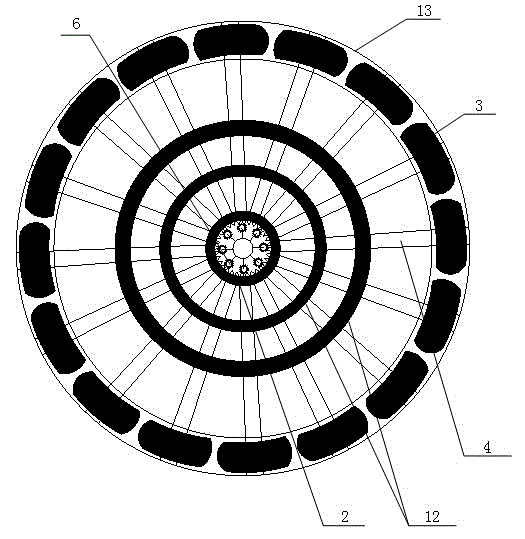
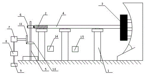
[0027] Such as figure 1 , 2 As shown, this embodiment provides a circular moment power generation system, the working principle of which is to convert the kinetic energy of the traction locomotive into electrical energy through a mechanical power generation device through the circular motion of the traction locomotive, so as to achieve the purpose of power generation, which is not only energy-saving and environmentally friendly, but also power generation Large quantity, small equipment footprint.

[0028] Specifically, the circular moment power generation system includes a circular traction track 13, a traction locomotive 3, a ring wheel 2, a rotating shaft 5, a drive gear 6, and a mechanical power generation system. Among them, the traction locomotive is set on the circular traction track, and performs circular motion along the circular traction track. In order to overcome the centrifugal force suffered by the traction locomotive when it makes circular motion, this embodimen...


PUM


Abstract

The invention discloses a circumferential torque electrical power generating system which solves the problems that an existing electrical power generating system is narrow in applied range, not capable of achieving energy saving and environmental protection and the like. The circumferential torque electrical power generating system comprises an annular traction track, traction engines, an annular wheel and internal teeth, wherein the traction engines are arranged on the annular traction track and make circular motion along the annular traction track, the annular wheel is placed in the annular traction track, stands on the ground through bearing columns and uses the center of the circle of the annular wheel as a rotating shaft to rotate, and the internal teeth are arranged on the inner wall of the annular wheel. The traction engines are connected with the annular wheel through connecting rods and used for driving the annular wheel to rotate. A rotating shaft which is perpendicular to the plane where the annular wheel is placed is arranged at the center of the circle of the annular wheel, and a driving gear which is meshed with the internal teeth of the annular wheel and used for driving the rotating shaft to rotate and a mechanical electrical power generating system used for converting mechanical energy of the rotating shaft into electric energy through a gear output mechanism are arranged at the upper end of the rotating shaft. The circumferential torque electrical power generating system is simple in structure, convenient to implement, large in generating capacity, capable of saving energy and protecting the environment, and particularly suitable for electricity generation during the electricity using peak times.

Description

technical field [0001] The invention relates to a power generation device, in particular to a circular moment power generation system. Background technique [0002] Power generation refers to the production process of converting water energy, thermal energy of petrochemical fuels (coal, oil, natural gas), nuclear energy, solar energy, wind energy, geothermal energy, ocean energy, etc. into electrical energy by using power generation power plants. In the prior art, commonly used power generation includes hydropower generation, wind power generation, solar power generation, nuclear power generation, and thermal power generation. Narrow, nuclear power generation and thermal power generation cause serious resource consumption and environmental pollution, which is inconsistent with the current energy conservation and environmental protection. [0003] Therefore, it has become an important task for those skilled in the art to develop an energy-saving and environment-friendly powe...

Claims


Application Information

Patent Timeline
Patent Type & Authority Applications(China)
IPC IPC(8): F03G3/00
Inventor 翁阳春
Owner 翁阳春
Why Eureka
Try Eureka