
Condensation heat exchange structure and gas water heater

A gas-fired water heater and condensing heat exchange technology, applied in air heaters, fluid heaters, lighting and heating equipment, etc., can solve problems such as low heat exchange efficiency of condensing heat exchange structures

Pending Publication Date: 2020-09-11
GREE ELECTRIC APPLIANCES INC
View PDF0 Cites 1 Cited by
  • Summary
  • Abstract
  • Description
  • Claims
  • Application Information

AI Technical Summary

Problems solved by technology

[0004] Based on this, it is necessary to provide a condensing heat exchange structure and a gas water heater to solve the problem of low heat exchange efficiency of the existing condensing heat exchange structure due to uneven distribution of flue gas.

Method used


Image

  • Condensation heat exchange structure and gas water heater
  • Condensation heat exchange structure and gas water heater
  • Condensation heat exchange structure and gas water heater

Examples


Embodiment Construction

[0043] In order to make the above objects, features and advantages of the present invention more comprehensible, specific implementations of the present invention will be described in detail below in conjunction with the accompanying drawings. In the following description, numerous specific details are set forth in order to provide a thorough understanding of the present invention. However, the present invention can be implemented in many other ways different from those described here, and those skilled in the art can make similar improvements without departing from the connotation of the present invention, so the present invention is not limited by the specific embodiments disclosed below.

[0044] In describing the present invention, it should be understood that the terms "center", "longitudinal", "transverse", "length", "width", "thickness", "upper", "lower", "front", " Back", "Left", "Right", "Vertical", "Horizontal", "Top", "Bottom", "Inner", "Outer", "Clockwise", "Counte...


PUM


Abstract

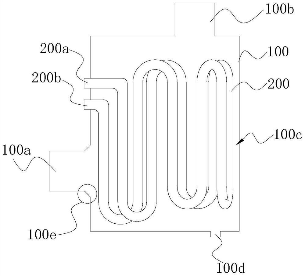
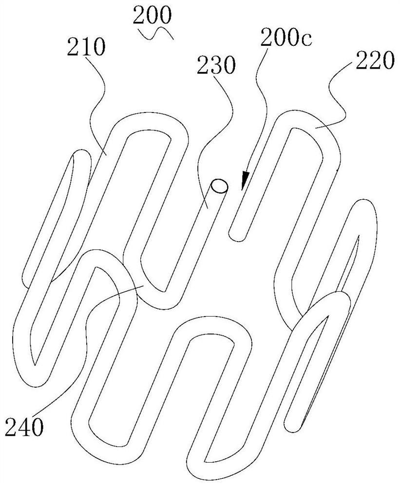
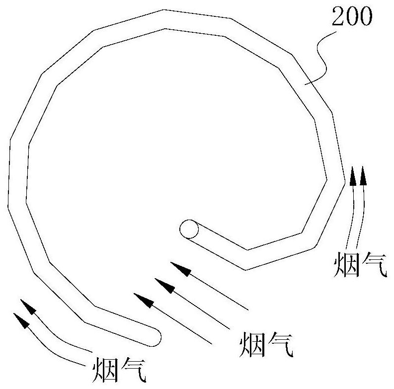
The invention relates to a condensation heat exchange structure and a gas water heater. The condensation heat exchange structure comprises a shell and a heat exchange pipe, wherein a smoke inlet is formed in the side wall of the shell, a smoke outlet located above the smoke inlet is further formed in the wall of the shell, the heat exchange pipe is circuitously bent along the trend of the cross section of the shell to form a hollow structure, an air passing gap is formed between the heat exchange pipe and the inner wall of the shell, and a water inlet and a water outlet are formed in the headand the tail of the heat exchange pipe respectively. The heat exchange pipe can be bent circuitously to form the hollow structure, so that the resistance borne by flue gas flowing through the gas passing gap is the same as the resistance borne by the flue gas flowing through a gas passing channel in the hollow structure, uniform distribution of the flue gas is guaranteed, most of the flue gas is prevented from flowing through the gas passing channel in the hollow structure, and the heat exchange efficiency of the condensation heat exchange structure is improved; and besides, the heat exchangepipe is circuitously bent in the direction of the cross section of the shell, the flowing path of cold water in the heat exchange pipe can be prolonged, the heat exchange time with smoke in the shellcan be prolonged, waste heat of the smoke can be fully utilized, and the heat exchange efficiency is improved.

Description

technical field [0001] The invention relates to the technical field of water heaters, in particular to a condensation heat exchange structure and a gas water heater. Background technique [0002] Traditional gas water heaters generally use the heat exchanger of their own heating components to absorb the heat generated by burning gas and transfer it to the cold water from the flow heat exchanger of the water inlet pipe. After heat exchange, the water temperature rises, and the hot water is discharged from the water outlet pipe. At the same time, the flue gas generated by the combustion is drawn out of the room by the fan through the flue gas chamber, and more than 10% of the heat is discharged with the flue gas, so the waste heat in the flue gas cannot be fully utilized, which causes a great waste of energy. In order to solve this problem, a condensing heat exchange structure is generally installed at the exhaust port of the fan to absorb the heat in the flue gas. [0003] T...

Claims


Application Information

Patent Timeline
IPC IPC(8): F24H8/00F24H9/00
CPCF24H8/00F24H8/006F24H9/0036Y02B30/00
Inventor 王志昂张果林钦林玉绵瞿福元
Owner GREE ELECTRIC APPLIANCES INC
Learn More