Continuous heating and defrosting air source heat pump control method

A technology of air source heat pump and control method, which is applied in the direction of climate sustainability, refrigerators, refrigeration components, etc., and can solve problems that affect heat pump heat supply, oscillation, and delay in stable operation.

Pending Publication Date: 2020-09-11
刘雄
View PDF1 Cites 4 Cited by
  • Summary
  • Abstract
  • Description
  • Claims
  • Application Information

AI Technical Summary

Problems solved by technology

When one main electronic expansion valve acts, it will inevitably affect the opening of the other main electronic expansion valve; The two corresponding main electronic expansion valves also work alternately; during this process, their openings also have a wide range of movements to meet the needs of the defrosting process; Simultaneous action, regulating the flow of refrigerant passing through the outdoor heat exchanger 4 and the outdoor heat exchanger 5, will inevitably affect each other, produc...

Method used


Image

  • Continuous heating and defrosting air source heat pump control method
  • Continuous heating and defrosting air source heat pump control method
  • Continuous heating and defrosting air source heat pump control method

Examples


Embodiment 1

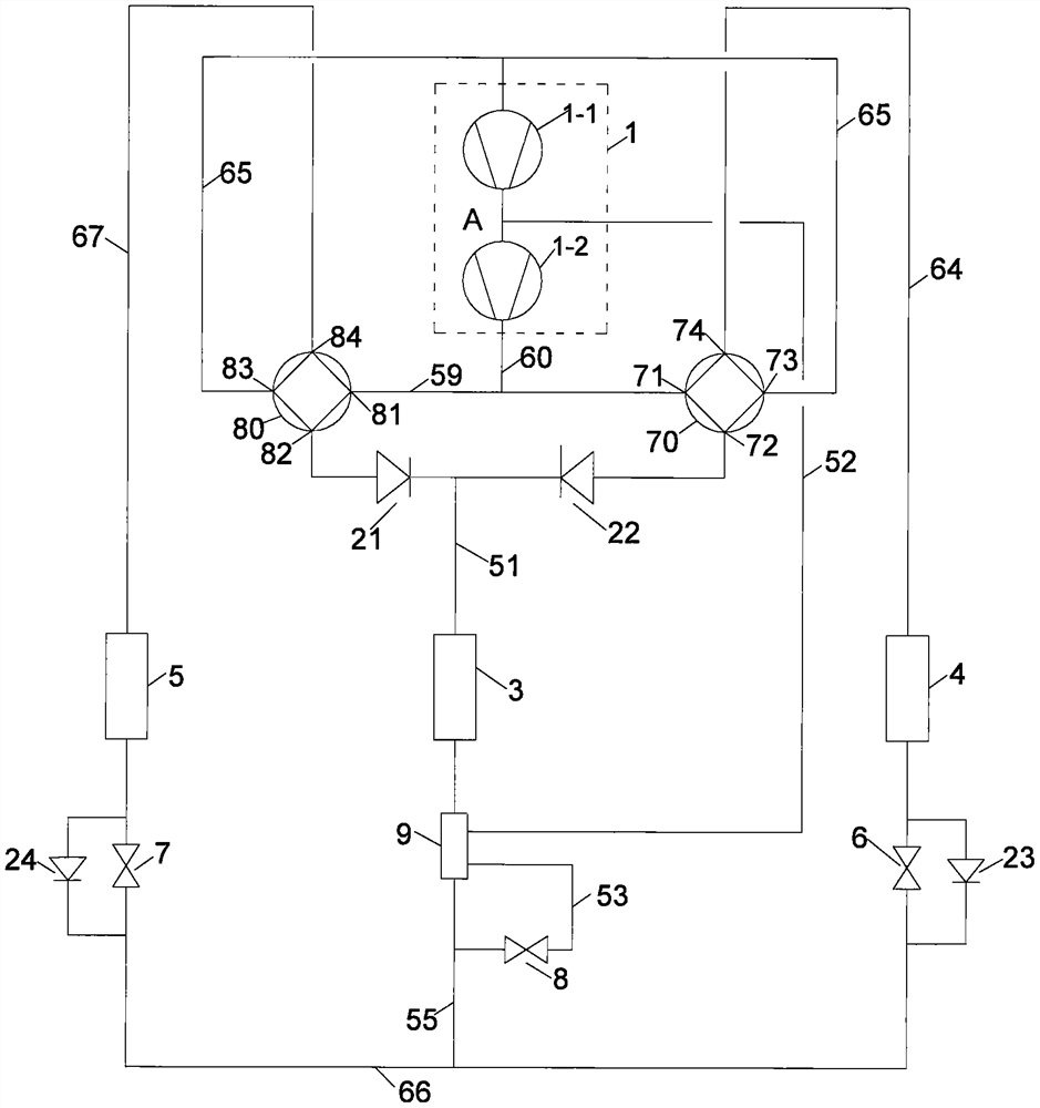
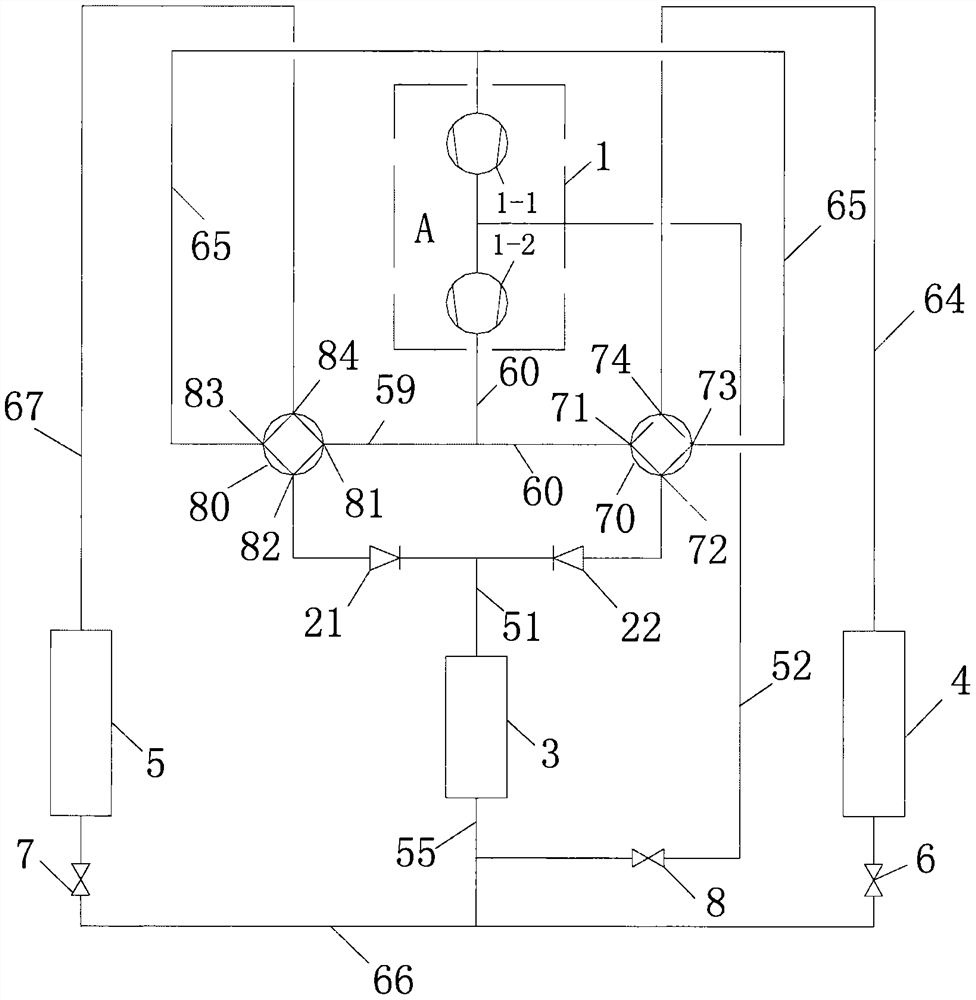
[0050] like figure 1 As shown, this embodiment is an application Figure 4 The shown patent is an air source heat pump capable of continuous heating and defrosting, which is used in occasions with heating needs. The whole device includes the following components: compression mechanism 1 (including low-pressure stage 1-1, high-pressure stage 1-2), four-way valve 70, four-way valve 80, main electronic expansion valve 6, main electronic expansion valve 7, outdoor replacement Heater 4, outdoor heat exchanger 5, heater 3; auxiliary electronic expansion valve 8, economizer 9.

[0051] Auxiliary electronic expansion valve 8 and economizer 9 form a gas injection enthalpy increasing system, and compression mechanism 1 is a compressor capable of realizing gas injection enthalpy increasing. However, when the climate is not very cold, the auxiliary electronic expansion valve 8 and the gas injection enthalpy increasing system formed by the economizer 9 can be used; like image 3 shown....

Embodiment 2

[0105] For fixed frequency compressors, figure 1 In the program shown in the defrosting process, if the second defrosting method is adopted, that is: when any group of outdoor heat exchangers meets the defrosting conditions, they will enter the defrosting state and defrosting them, and the defrosting ends After that, continue to defrost another group of outdoor heat exchangers; when the two groups of outdoor heat exchangers have defrosted, the air source heat pump will enter the normal operation state again.

[0106] If during the normal operation of the air source heat pump, in the outdoor heat exchanger 4 and the outdoor heat exchanger 5, it is first detected that the outdoor heat exchanger 4 meets the defrosting conditions and needs to enter the defrosting state to defrost it; figure 1 The basic control requirements of the scheme shown in the second defrosting mode are as follows.

[0107] (1) During the normal operation of the air source heat pump, in the outdoor heat e...

Embodiment 3

[0135] For the inverter compressor, if during the normal operation of the air source heat pump, in the outdoor heat exchanger 4 and the outdoor heat exchanger 5, it is first detected that the outdoor heat exchanger 4 meets the defrosting condition and needs to enter the defrosting state When defrosting; figure 1 The basic control requirements of the scheme shown in the first defrosting mode are as follows.

[0136] (1) During the normal operation of the air source heat pump, in the outdoor heat exchanger 4 and the outdoor heat exchanger 5, when the outdoor heat exchanger 4 meets the defrosting conditions and needs to enter the defrosting state before defrosting, the compression Engine 1 is unloaded first; the controller records the opening values ​​of main electronic expansion valves 6 and 7 before unloading at the same specified time before unloading of compressor 1; after unloading of compressor 1, it is stable after one continuous operation time period; when running in th...


PUM


Abstract

The invention discloses a continuous heating and defrosting air source heat pump control method. Low-voltage protection of a heat pump system is actively shielded during the period of defrosting, andthe low-voltage protection is started after the defrosting period; when any group of outdoor heat exchangers of all outer heat exchangers meets a defrosting condition and enters a defrosting state, acontroller records pre-defrosting opening values of all main electronic expansion valves matched with a first group of outdoor heat exchangers to be defrosted at the same specified time before a four-way valve is switched; the first group of outdoor heat exchangers enters the defrosting state after the four-way valve is switched; and the main electronic expansion valves opening matched with the first group of outdoor heat exchangers is a specified defrosting opening, and remaining main electronic expansion valves are respectively regulate opening according to outlet superheat degree of the outdoor heat exchangers matched with the main electronic expansion valves in the defrosting period of the first group of outdoor heat exchangers. The method is characterized in that heat can be providedin the defrosting, the operation of the heat pump is more stable, the defrosting time can be shortened, and the heating load of the heat pump is improved.

Description

technical field [0001] The invention relates to an air source heat pump control method capable of continuous heating and defrosting, and belongs to the technical field of refrigeration. Background technique [0002] The applicant of the present invention was authorized on June 29, 2016, and the invention patent with the patent number 201110355023.0 proposed a refrigerant three-way flow conversion device, and its system composition is as follows Figure 4 As shown, this patent can be used to design an air source heat pump that can realize continuous heating and defrosting, such as Figures 1 to 3 shown. exist figure 1 In the system shown, the air source heat pump has at least two sets of outdoor heat exchangers 4 and 5; when the outdoor heat exchanger 4 needs to defrost, the four-way valve 70 switches; and the four-way valve 80 does not switch, the outdoor heat exchanger 5 is still working normally, absorbing heat from the outdoor air, part of the absorbed heat is supplied...

Claims


Application Information

Patent Timeline
IPC IPC(8): F25B47/02F25B41/04F25B41/06F25B49/02
CPCF25B47/025F25B49/02F25B2600/25F25B2600/2513Y02B30/70
Inventor 刘雄
Owner 刘雄
Why Eureka
Try Eureka