Coupling injection enthalpy-increasing air source heat pump system

A technology of air source heat pump and air injection to increase enthalpy, which is applied in heating systems, heat pumps, space heating and ventilation, etc. It can solve the problems of large return flow of refrigerant, large heat loss, and large energy consumption of electric heating defrosting. , to achieve the effect of rational utilization of energy, increase of heat energy, and reduction of defrosting time

Inactive Publication Date: 2012-07-11
CHONGQING UNIV
View PDF11 Cites 20 Cited by
  • Summary
  • Abstract
  • Description
  • Claims
  • Application Information

AI Technical Summary

Problems solved by technology

[0003] There are three commonly used defrosting methods for air source heat pumps: electric heating defrosting, reverse cycle defrosting and hot gas bypass defrosting. Source heat pumps rarely use this defrosting method
Reverse cycle defrosting was widely used in early heat pump systems due to its fast defrosting speed, but this defrosting method has the following disadvantages: 1. The suction and discharge pressure of the compressor changes drastically, which greatly affects its performance , the return flow of refrigerant in the system is large; 2. The functions of the two heat exchangers are frequently switched, and the heat loss is large, resulting in large fluctuations in the temperature of the building water supply; 3. The four-way reversing valve operates frequently, and the reliability is low
[0005] The obvious disadvantages of this air source heat pump system are: in the defrosting mode, the heating stops, and continuous heating cannot be provided; Insufficient heat, resulting in long defrosting time
[0006] like figure 1 As shown, due to the existing hot gas bypass defrosting process, the high-temperature working medium steam at the outlet of compressor 1 enters the outdoor heat exchanger 12 for defrosting through the bypass solenoid valve 2, and a large amount of steam will be generated at the outlet of the outdoor heat exchanger 12. In this way, the amount of liquid accumulated in the first gas-liquid separator 18 increases, resulting in a decrease in the flow rate of the working medium and a decrease in the heating capacity of the system; when the flow rate of the liquid refrigerant in the outdoor heat exchanger is large, the compressor prone to liquid shock
Therefore, the traditional hot gas bypass defrosting air source heat pump system is difficult to be widely used in large air-cooled heat pump units

Method used


Image

  • Coupling injection enthalpy-increasing air source heat pump system
  • Coupling injection enthalpy-increasing air source heat pump system
  • Coupling injection enthalpy-increasing air source heat pump system

Examples


Embodiment Construction

[0020] Below in conjunction with accompanying drawing and embodiment the present invention will be further described:

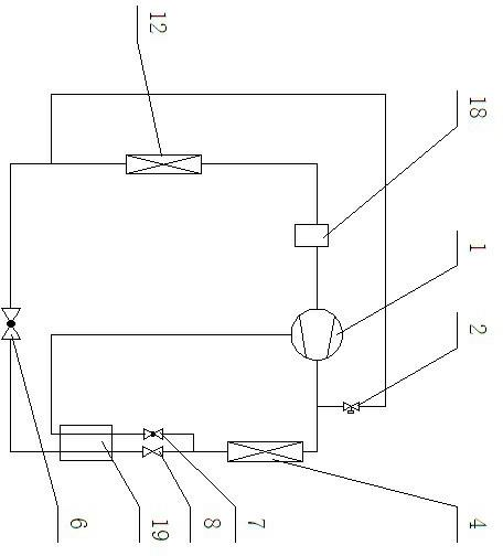
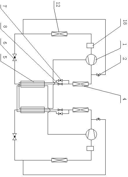
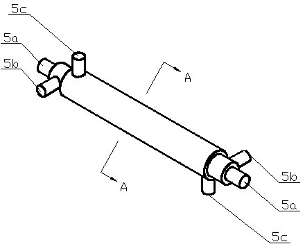
[0021] Such as figure 2 As shown, the present invention includes an air source heat pump system for increasing enthalpy by air injection. The air source heat pump system for increasing enthalpy by air injection has a compressor 1, an indoor heat exchanger 4, a refrigeration circuit, an air supply circuit, and a bypass defrosting branch. The outlet of 1 is connected with the inlet of indoor heat exchanger 4, and a bypass defrosting branch is set between the outlet of compressor 1 and the inlet of indoor heat exchanger 4, and the bypass defrosting branch directly enters through the bypass solenoid valve 2 The main point of the entrance of the outdoor heat exchanger 12 is that it has two subsystems of the air-injection enthalpy-increasing air source heat pump and two three-pipe heat exchangers 5, and the refrigeration circuit starts from the outlet of the indoo...


PUM


Abstract

The invention relates to an air source heat pump system, which comprises two injection enthalpy-increasing air source heat pump subsystems and two triple-sleeve heat exchangers. A refrigerating loop starts from an outlet of an indoor heat exchanger of each subsystem, runs through a flow regulating valve and enters a suction opening of a compressor via the triple-sleeve heat exchanger, a first throttling valve, an outdoor heat exchanger and a first gas and liquid separator of the subsystem; and an air supplementing loop is branched at the outlet of the indoor heat exchanger of each subsystem and enters an air supplementing opening of the compressor of the subsystem via a second throttling valve, the triple-sleeve heat exchanger and a coupling subsystem triple-sleeve heat exchanger of the subsystem. By the aid of the coupling injection enthalpy-increasing air source heat pump system, problems that heat cannot be supplied continuously during defrosting in a low-temperature environment and defrosting time is long are solved, energy is reasonably utilized, heat required by defrosting is increased, and problems that the quantity of accumulated liquid refrigerating working media generated by an outdoor heat exchanger of a defrosting subsystem is increased, a compressor is impacted by liquid and the like are solved.

Description

technical field [0001] The invention relates to an air source heat pump system. Background technique [0002] Air source heat pump is a kind of heating equipment that utilizes low-grade energy in the ambient air by consuming a part of high-grade energy. It belongs to new energy technology and has the dual advantages of energy saving and environmental protection. It is currently the main source of renewable energy for building hot water supply. Form, the application prospect is broad. However, air source heat pumps are greatly affected by meteorological conditions, especially in humid and cold areas with relatively high air humidity in winter. This will seriously affect the performance of the heat pump system. The air source heat pump system of air supplementation and enthalpy increase in the existing research has improved the operating performance of the heat pump system under low temperature conditions to a certain extent, and effectively expanded the climate adaptation r...

Claims


Application Information

Patent Timeline
Patent Type & Authority Applications(China)
IPC IPC(8): F25B30/06F25B41/04F25B41/06F25B47/02F24D15/04
Inventor 李夔宁郭春雷周伟郭军峰李进
Owner CHONGQING UNIV
Why Eureka
Try Eureka