UAV-borne semi-aerial transient electromagnetic and magnetic method cooperative acquisition system and method

A transient electromagnetic and acquisition system technology, applied in the field of geophysical exploration, can solve the problems of receiving data deviation, low data acquisition efficiency, and affecting normal data acquisition, so as to reduce the influence of wind factors, improve data acquisition efficiency, and improve appearance The structure is simple and beautiful

Active Publication Date: 2021-08-27
SHANDONG UNIV
View PDF10 Cites 0 Cited by
  • Summary
  • Abstract
  • Description
  • Claims
  • Application Information

AI Technical Summary

Problems solved by technology

In terms of receiving coil design, in order to avoid interference from the aircraft, the general carrying method is mostly a pod-type soft connection, but this method is susceptible to interference from external movement characteristics, especially when the movement speed is not as fast as a helicopter. For example, Due to changes in wind force, weather factors, improper operation of the UAV operator, etc., the receiving coil is always in motion with the UAV in the air, which will cause wind resistance, shaking, cutting magnetic force lines, etc., resulting in large deviations in the received data, and the reliability of the data is difficult. Guarantee; the circuit system, amplification system, and attitude system of the traditional receiving coil are mostly arranged in the center of the coil, occupying the internal data acquisition area of ​​the receiving coil, and its system is also susceptible to interference, which affects the normal data collection; the traditional attitude sensor can only collect the attitude of the coil In actual field operations, more comprehensive information is needed to provide support for data interpretation, such as air pressure, temperature, etc.
In terms of receiver design, the existing receivers are large in size and high in mass, resulting in excessive external loads on the UAV when carrying the receiver, which cannot guarantee the flight speed of the UAV, and will reduce the speed of the UAV. The flight time of the drone is low, and the data collection efficiency is low and there are potential safety hazards; carrying heavy loads for a long time will easily cause hardware loss of the drone, increase maintenance costs, and reduce the service life of the drone; traditional transient electromagnetic receivers are not easy to carry During data collection, the receiver is under the drone, and there are certain difficulties in data transmission. In addition, sometimes there are mountains blocking the signal, which makes it impossible to achieve effective quality control of the collected data.

Method used


Image

  • UAV-borne semi-aerial transient electromagnetic and magnetic method cooperative acquisition system and method
  • UAV-borne semi-aerial transient electromagnetic and magnetic method cooperative acquisition system and method
  • UAV-borne semi-aerial transient electromagnetic and magnetic method cooperative acquisition system and method

Examples


Embodiment 1

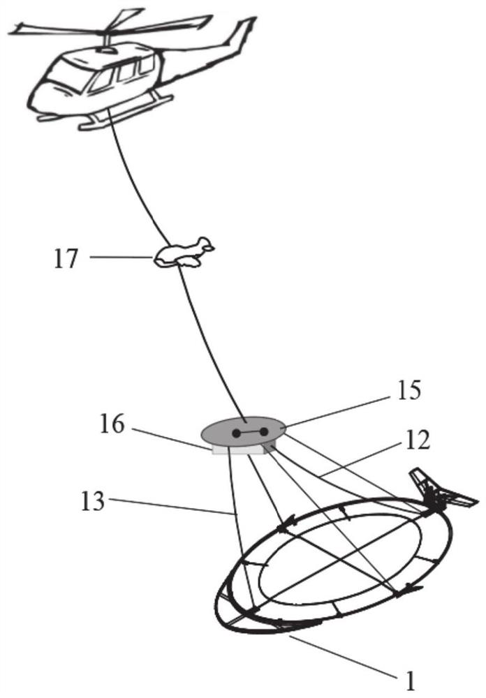
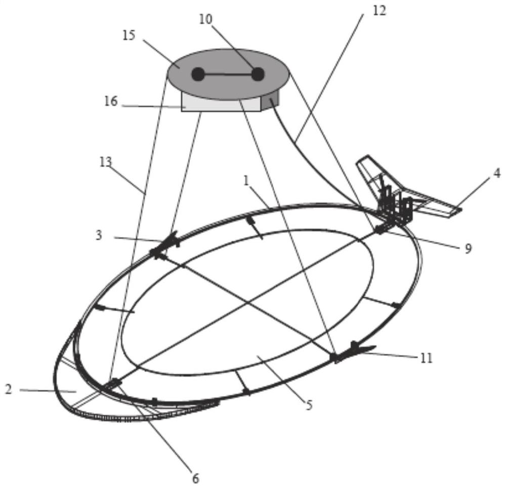
[0057] Such as Figure 1-7 As shown, Embodiment 1 of the present disclosure provides a UAV-borne semi-aerial transient electromagnetic and magnetic method cooperative acquisition system, including a transient electromagnetic receiving coil part, a magnetic sensor part and an acquisition recorder part.

[0058] (1) Transient electromagnetic receiving coil part: including fish-shaped receiving coil and various components mounted on the coil.

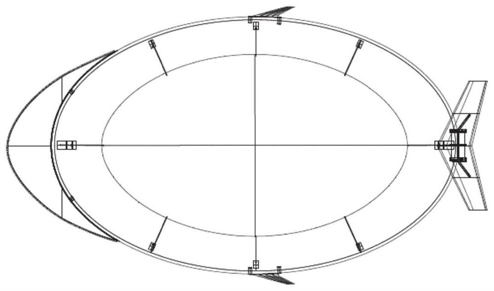
[0059] The fish-shaped receiving coil includes a fish-shaped coil skeleton 1 , a coil head 2 , a coil side wing 3 , a coil tail wing 4 , an oval canvas 5 and a connecting ring buckle 6 .

[0060] The coil tail is designed as a cavity structure for components such as built-in amplifiers, GPS and its data transmission unit. The structure includes a horizontal tail 7 and three vertical tails 8 .

[0061] The components mounted on the coil include attitude sensor 9 , GPS 10 , amplifier 11 , data transmission unit 12 , insulated connection rop...

Embodiment 2

[0089] Embodiment 2 of the present disclosure provides an unmanned aerial vehicle-borne semi-aerial transient electromagnetic and magnetic method collaborative acquisition method, including the following steps:

[0090] Taking the plane where the receiving coil is located as the reference plane, the receiving coil is wound horizontally with a fish-shaped receiving coil frame as the ring. When the magnetic induction line of the underground magnetic field passes through the receiving coil, electromagnetic induction is caused inside the receiving coil that is energized, and at the same time the magnetic field The magnetic signal on the ground is collected by the magnetic sensor, and the corresponding electrical signal will be observed in the data transmission unit of the coil tail;

[0091] Due to the small value of this electrical signal, the transient electromagnetic signal and magnetic field signal are processed by the amplifier at the front end of the coil tail, and the analog...


PUM


Abstract

The disclosure provides a UAV-borne semi-aerial transient electromagnetic and magnetic method cooperative acquisition system and method, including a drone, a transient electromagnetic receiving coil, a magnetic sensor and an acquisition recorder; the magnetic sensor is carried on On the drone and connected to the acquisition recorder, the electromagnetic receiving coil is connected to the drone through an insulated wire; the transient electromagnetic receiving coil at least includes an elliptical coil skeleton, and the end of one end of the long axis of the elliptical coil skeleton is provided with a coil The head, the other end of the long axis is provided with a coil tail, and the two ends of the short axis of the elliptical coil frame or the positions close to the two ends of the short axis are symmetrically provided with coil flanks; the receiving coil described in the present disclosure adopts a streamlined structure design, During the flight, the influence of wind factors can be effectively reduced, and the quality of data collection can be improved.

Description

technical field [0001] The present disclosure relates to the technical field of geophysical detection, and in particular to a UAV-borne semi-aerial transient electromagnetic and magnetic collaborative acquisition system and method. Background technique [0002] The statements in this section merely provide background information related to the present disclosure and may not necessarily constitute prior art. [0003] Transient electromagnetic method is a geophysical method widely used in the fields of resource exploration, geological structure exploration, hydrological survey and groundwater survey. Aeronautical transient electromagnetic uses the helicopter system to place the entire transient electromagnetic transceiver device in the air for detection. It has the characteristics of flexibility and high detection efficiency, and its development is relatively mature in the West. The semi-aerial transient electromagnetic method is a new method developed on the basis of the gro...

Claims


Application Information

Patent Timeline
Patent Type & Authority Patents(China)
IPC IPC(8): G01V3/10
CPCG01V3/10
Inventor 孙怀凤张诺亚赵友超杨静杨洋
Owner SHANDONG UNIV
Why Eureka
Try Eureka