Nuclear explosion radioactive contamination prediction method based on gas-solid two-phase flow simulation

A prediction method and radioactive technology, applied in special data processing applications, instruments, electrical digital data processing, etc., can solve the problems of gas-solid separation effect, unreasonable description of turbulent diffusion effect, etc.

Pending Publication Date: 2020-09-11
NORTHWEST INST OF NUCLEAR TECH
View PDF3 Cites 1 Cited by
  • Summary
  • Abstract
  • Description
  • Claims
  • Application Information

AI Technical Summary

Problems solved by technology

[0006] In order to solve the technical problem of unreasonable description of the gas-solid separation effect and turbulent diffusion effect in the existing nuclear explosion radioactive smoke cloud particle atmospheric transport and settlement simulation method, the present invention provides a radioactive contamination numerical simulation method based on the gas-solid two-phase simulation method

Method used


Image

  • Nuclear explosion radioactive contamination prediction method based on gas-solid two-phase flow simulation
  • Nuclear explosion radioactive contamination prediction method based on gas-solid two-phase flow simulation
  • Nuclear explosion radioactive contamination prediction method based on gas-solid two-phase flow simulation

Examples


Embodiment 1

[0150] Set the explosion equivalent W to 1.65kt; the fission ratio to 1; the height h of the center of the explosion point from the ground to 3m; p 2.6×10 3 kg / m 3 ; wind speed at different heights is shown in Table 1; boundary layer thickness H b is 1500m; Mourning length L is -10; surface roughness r 0 The calculation interval of radioactive particles is -3000≤x≤48000, -3000≤y≤28000, the unit is m; the spatial resolution of the recording grid is 100m×100m; the calculation cut-off time is 24hr; the number of simulated particles N is 10 7 indivual;

[0151] Table 1

[0152]

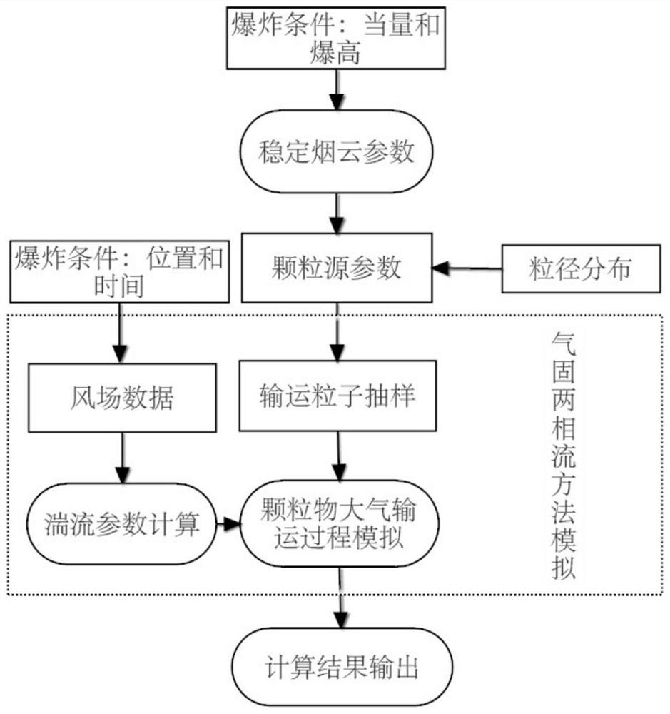
[0153] The flow chart of the prediction method in this embodiment is as follows figure 1 shown, including the following steps:

[0154] 1) Calculation condition initialization processing

[0155] 1.1) Initialize the calculation condition parameters such as the number of simulated particles, cut-off time, calculation range, and grid division;

[0156] 1.2) Read in the meteorological parameters r...

Embodiment 2

[0218] The difference from Example 1 is that step 3) the calculation of turbulence parameters is moved to step 4) the first step of simulating the transport and settlement process of radioactive particles, and the turbulence parameters of radioactive particles are calculated at each time step, so as to more accurately calculate the particle position, The movement speed and force situation can improve the prediction accuracy of radioactive particle contamination.


PUM

PropertyMeasurementUnit
Densityaaaaaaaaaa
Thicknessaaaaaaaaaa

Abstract

The invention provides a radioactive contamination numerical simulation method based on a gas-solid two-phase simulation method, and solves the problem of unreasonable description of a gas-solid separation effect and a turbulence diffusion effect in an existing nuclear explosion radioactive smoke cloud particle atmospheric transportation and settlement simulation method. The method comprises the following steps: 1) setting a contamination distribution calculation area according to explosion equivalent and average wind speed, setting the total number of simulated particles and recording grid resolution; 2) establishing initial space distribution of nuclear explosion radioactive particles by adopting a stable smoke cloud model; 3) calculating turbulence parameters; (4) simulating the atmospheric transportation and sedimentation process of a certain radioactive particle in the stable smoke cloud by using a gas-solid two-phase flow method until the radioactive particle falls to the groundor escapes from the calculation boundary, and adopting a time advancing principle in the gas-solid two-phase flow method, and (5) according to all the calculated sedimentation positions of the radioactive particles, performing statistics to give a distribution result of ground surface contamination.

Description

technical field [0001] The invention relates to a nuclear explosion radioactive contamination prediction simulation technology, in particular to a nuclear explosion radioactive contamination prediction method based on gas-solid two-phase flow simulation. Background technique [0002] Nuclear explosion effects mainly include shock wave, optical radiation, early nuclear radiation, nuclear electromagnetic pulse and radioactive contamination effects. Radioactive contamination is one of the important killing factors of nuclear explosion, which has the characteristics of long duration and wide range of effects. During a ground nuclear explosion, a large amount of molten and vaporized soil material is drawn into the smoke cloud, causing a large number of particles with larger diameters in the smoke cloud. The settlement of these larger radioactive particles mainly occurs in a local area closer to the explosion point, and will Severe radioactive contamination is formed within a ran...

Claims


Application Information

Patent Timeline
IPC IPC(8): G06F30/20G06F119/14
CPCG06F30/20G06F2119/14Y02E30/30
Inventor 卓俊黄流兴牛胜利朱金辉商鹏李夏至
Owner NORTHWEST INST OF NUCLEAR TECH
Why Eureka
Try Eureka