
Rotor structure of a permanent magnet motor

A technology of rotor structure and permanent magnet motor, applied in the direction of motor, magnetic circuit shape/style/structure, magnetic circuit rotating parts, etc., can solve problems such as permanent magnet demagnetization fault, rotor eccentricity problem, permanent magnet motor operation safety impact, etc. , to achieve the effects of reducing thermal stress unbalance, balancing axial temperature distribution, and avoiding local loss of magnetism

Active Publication Date: 2022-01-11
BEIJING JIAOTONG UNIV
View PDF7 Cites 0 Cited by
  • Summary
  • Abstract
  • Description
  • Claims
  • Application Information

AI Technical Summary

Problems solved by technology

Due to the space limitation of the application, the power density of the permanent magnet motor is high, and the heat dissipation conditions and cooling structure are restricted, resulting in high temperature in the local position of the motor, and the permanent magnet near the axial center of the motor is seriously heated, resulting in axial heat dissipation of the permanent magnet. Unbalanced stress can easily lead to rotor eccentricity and partial demagnetization faults of permanent magnets in severe cases, which will seriously affect the operation safety of permanent magnet motors

Method used


Image

  • Rotor structure of a permanent magnet motor
  • Rotor structure of a permanent magnet motor
  • Rotor structure of a permanent magnet motor

Examples


Embodiment Construction

[0021] Embodiments of the present invention are described in detail below, and examples of the embodiments are shown in the drawings, wherein the same or similar reference numerals denote the same or similar elements or elements having the same or similar functions throughout. The embodiments described below by referring to the figures are exemplary only for explaining the present invention and should not be construed as limiting the present invention.

[0022] Those skilled in the art will understand that unless otherwise stated, the singular forms "a", "an", "" and "the" used herein may also include plural forms. It should be further understood that the word "comprising" used in the description of the present invention refers to the presence of features, integers, steps, operations, elements and / or components, but does not exclude the presence or addition of one or more other features, integers, Steps, operations, elements, components and / or groups thereof. It will be under...


PUM


Abstract

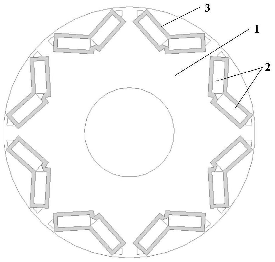
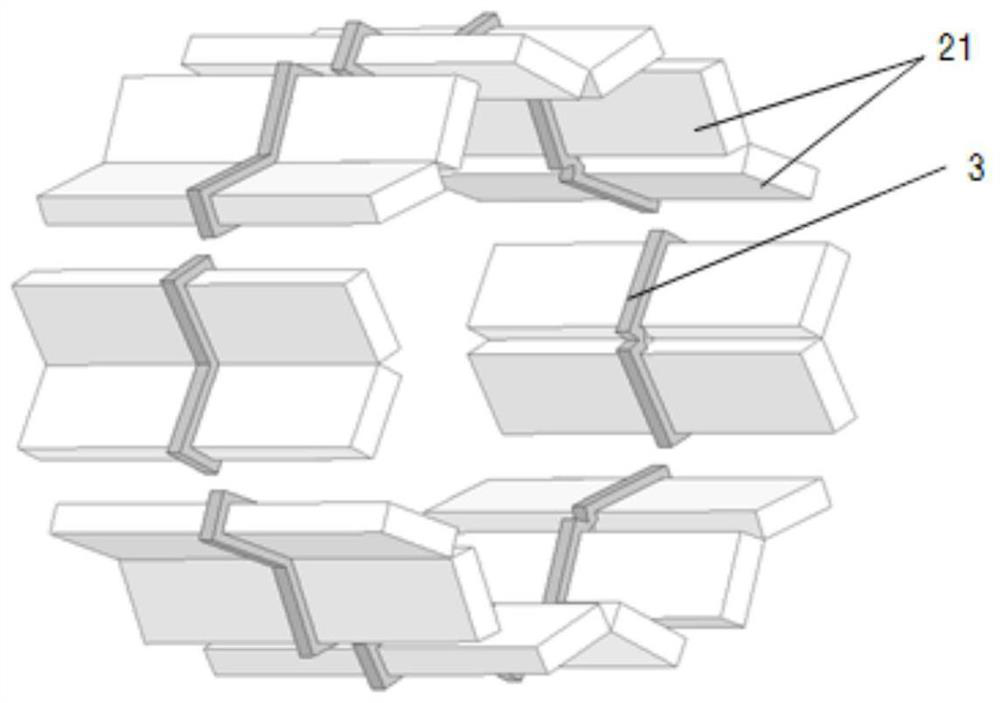
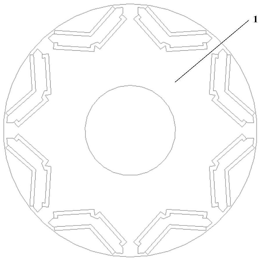
The invention provides a rotor structure of a permanent magnet motor, which can balance the axial temperature distribution of the permanent magnets, including a rotor core, a plurality of permanent magnets and eddy current rings; a plurality of permanent magnets and eddy current rings are embedded in the rotor core; The iron core extends axially and is arranged around the axis of the rotor iron core. The section of each permanent magnet is V-shaped; the outer surface of each permanent magnet is fitted with an eddy current ring, and the eddy current ring is located in the axial middle of the permanent magnet. The rotor structure provided by the present invention reduces the eddy current loss where the permanent magnet is wrapped by the eddy current ring by putting the eddy current ring on the axial center of the permanent magnet, thereby balancing the axial temperature distribution of the permanent magnet and reducing thermal stress. Problems with permanent magnet motor failure caused by balance. At the same time, the eddy current ring can reduce the maximum temperature of the permanent magnet, avoid the problem of partial demagnetization of the permanent magnet caused by local high temperature, and improve the safety and stability of the permanent magnet motor.

Description

technical field [0001] The invention relates to the technical field of permanent magnet motors, in particular to a rotor structure of permanent magnet motors. Background technique [0002] At present, the application fields of permanent magnet motors are more and more extensive, and they have broad prospects in aerospace, instrumentation, electric vehicles, wind power and other fields. While pursuing high efficiency and energy saving, more attention should be paid to the stability and reliability of permanent magnet motors. Due to the space limitation of the application, the power density of the permanent magnet motor is high, and the heat dissipation conditions and cooling structure are restricted, resulting in high temperature in the local position of the motor, and the permanent magnet near the axial center of the motor is seriously heated, resulting in axial heat dissipation of the permanent magnet. If the stress is unbalanced, it will easily lead to rotor eccentricity a...

Claims


Application Information

Patent Timeline
Patent Type & Authority Patents(China)
IPC IPC(8): H02K1/27H02K1/32
CPCH02K1/27H02K1/32Y02T10/64
Inventor 李伟力张美巍李金阳罗轼凡黄雪莲汤昊岳张富全沈稼丰高晗璎李栋邱洪波
Owner BEIJING JIAOTONG UNIV
Learn More