
Compass

A compass and edge line technology, applied in compass, measuring device, surveying and navigation, etc., can solve time-consuming problems, achieve the effect of reducing energy consumption, reducing time consumption, and improving determination accuracy

Inactive Publication Date: 2020-09-11
S M 克洛波夫
View PDF5 Cites 0 Cited by
  • Summary
  • Abstract
  • Description
  • Claims
  • Application Information

AI Technical Summary

Problems solved by technology

Said way is time consuming
Furthermore, the described approach requires a high degree of concentration

Method used


Image

  • Compass
  • Compass

Examples


Embodiment Construction

[0029] The compass is used according to the invention as follows:

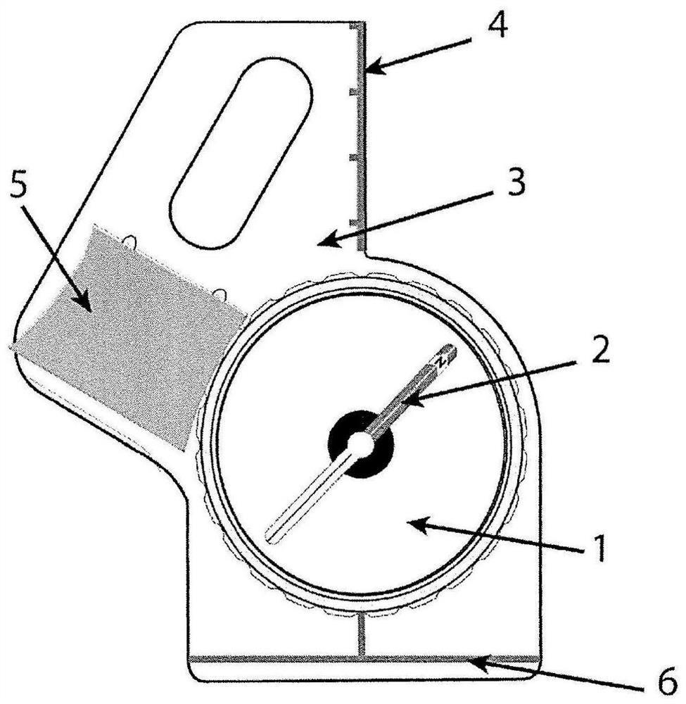
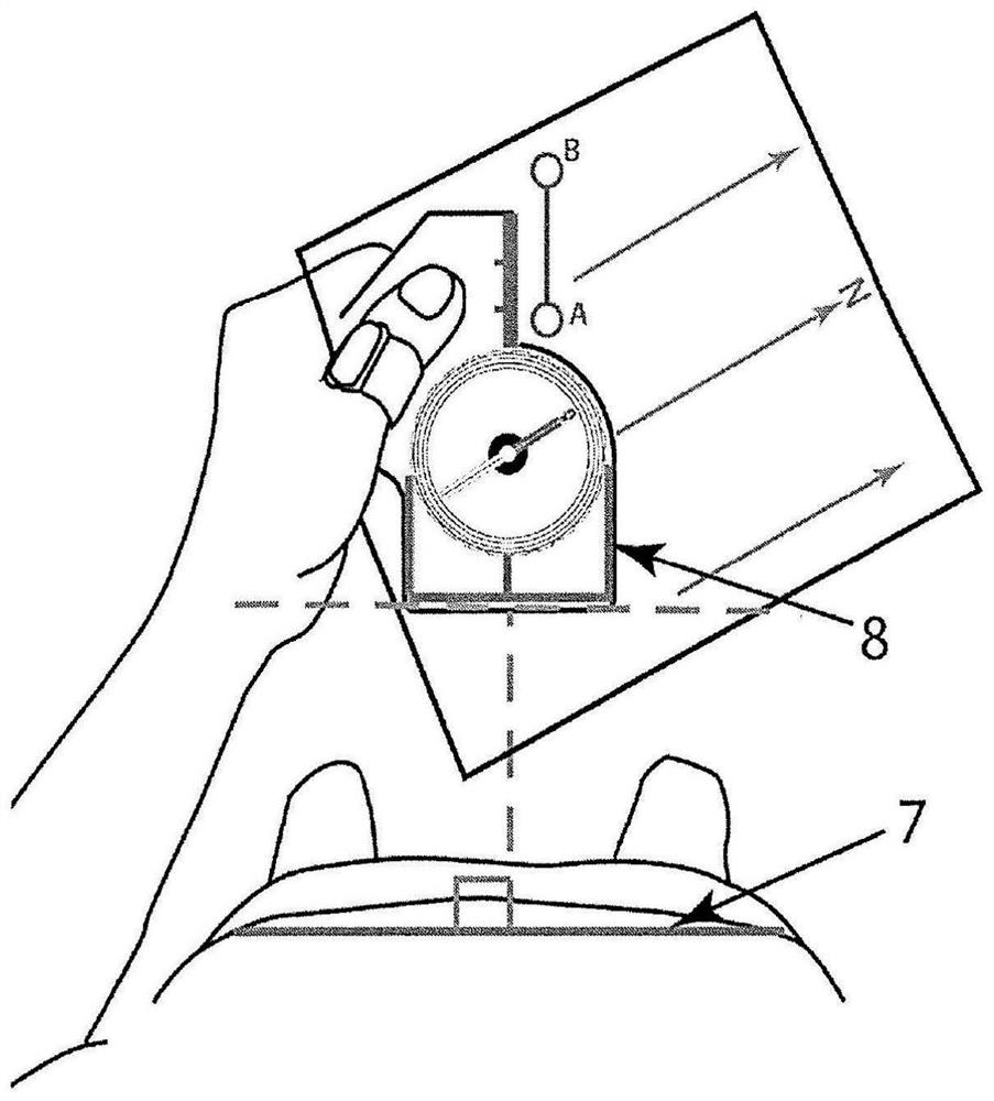
[0030] The loop 3 surrounds the thumb, in this case the left thumb. The map is pressed onto the plate 2 through the opening 6 with the thumb. The map is turned. The edge line 4 of the direction of movement must coincide with the desired direction on the map. The runner turns the housing 1 with his right hand until the north-south direction on the housing 1 coincides with the north-south direction on the map. The runner then corrects the arrangement of the compass relative to his body according to the edge line 5 . The runner's task here is to achieve the parallelism of this edge line to the line on which the runner's shoulders lie. The runner then turns. The compass needle 7 and the north-south-direction on the housing 1 must coincide. The runner extends the edge line 4 in his head with his line of sight and determines the line in the field for the direction of movement. The runner runs and controls the...


PUM


Abstract

The invention relates to the field of terrain navigation and can be used in orienteering. A compass comprises a capsule having a magnetic needle and a baseplate, said baseplate having a strap (belt) attached thereto so that the compass can be worn on a finger, wherein the baseplate has a direction of travel edge line, an extension of which runs through the center of the capsule and through a second edge line that is perpendicular to the direction of travel edge line and disposed behind the capsule and at a distance therefrom. Furthermore, the compass comprises additional edge lines running parallel to the direction of travel edge line. The problem of interest consists in decreasing error when transferring the direction of travel from a compass to terrain.

Description

technical field [0001] The invention relates to a compass for orienting in the field. The invention can be applied to orienteering. Background technique [0002] Orienteering is a type of sport in which the athlete (runner) has to pass through several checkpoints (KP) with the aid of an orienteering map and a compass. Checkpoints are set in the wild. Grades are usually determined based on the required passing time. [0003] The task that exists for the athlete in the field is to cover a section of the distance from KP A to KP B (movement along the azimuth angle) without changing the direction. The athlete is provided with an orienteering map for this purpose. Inscribe (denote) KP A and В on said map. KP A and В are connected to each other by a line (line segment AB). Also marked is the line on which magnetic north (magnetic north direction) is oriented on the map. The angle between the line of magnetic north on the map and the line segment AB is called the map azimuth...

Claims


Application Information

Patent Timeline
IPC IPC(8): G01C17/04
CPCG01C17/04
Inventor S·M·克洛波夫A·S·克洛波夫M·T·菲利蒙诺夫
Owner S M 克洛波夫
Learn More