
Calculating method of mirror field optical efficiency of tower type solar thermoelectric system

A tower solar and thermoelectric system technology, applied in computing, electrical digital data processing, special data processing applications, etc., can solve problems such as low efficiency, high difficulty, and increased computational complexity

Active Publication Date: 2013-02-13
ZHEJIANG UNIV
View PDF3 Cites 25 Cited by
  • Summary
  • Abstract
  • Description
  • Claims
  • Application Information

AI Technical Summary

Problems solved by technology

However, the calculation process of the above method in the prior art is relatively complicated and inefficient, and it is difficult to calculate the overflow efficiency, especially the calculation time doubles with the expansion of the mirror field.
In the prior art, there is also a method of calculating the optical efficiency of the mirror field by using the ray tracing method. The advantage of this method is that the position of each ray and each heliostat can be intuitively and clearly judged by tracing the rays scattered in the mirror field. relationship, and finally can conveniently calculate the overflow efficiency, and at the same time obtain the heating schematic diagram of the heat absorber, but the disadvantage of the existing method of calculating the optical efficiency of the mirror field by using the ray tracing method is that the amount of calculation will also increase with the mirror of the mirror field. The number increases, the area of ​​the mirror field expands and other factors increase

Method used


Image

  • Calculating method of mirror field optical efficiency of tower type solar thermoelectric system
  • Calculating method of mirror field optical efficiency of tower type solar thermoelectric system
  • Calculating method of mirror field optical efficiency of tower type solar thermoelectric system

Examples


Embodiment Construction

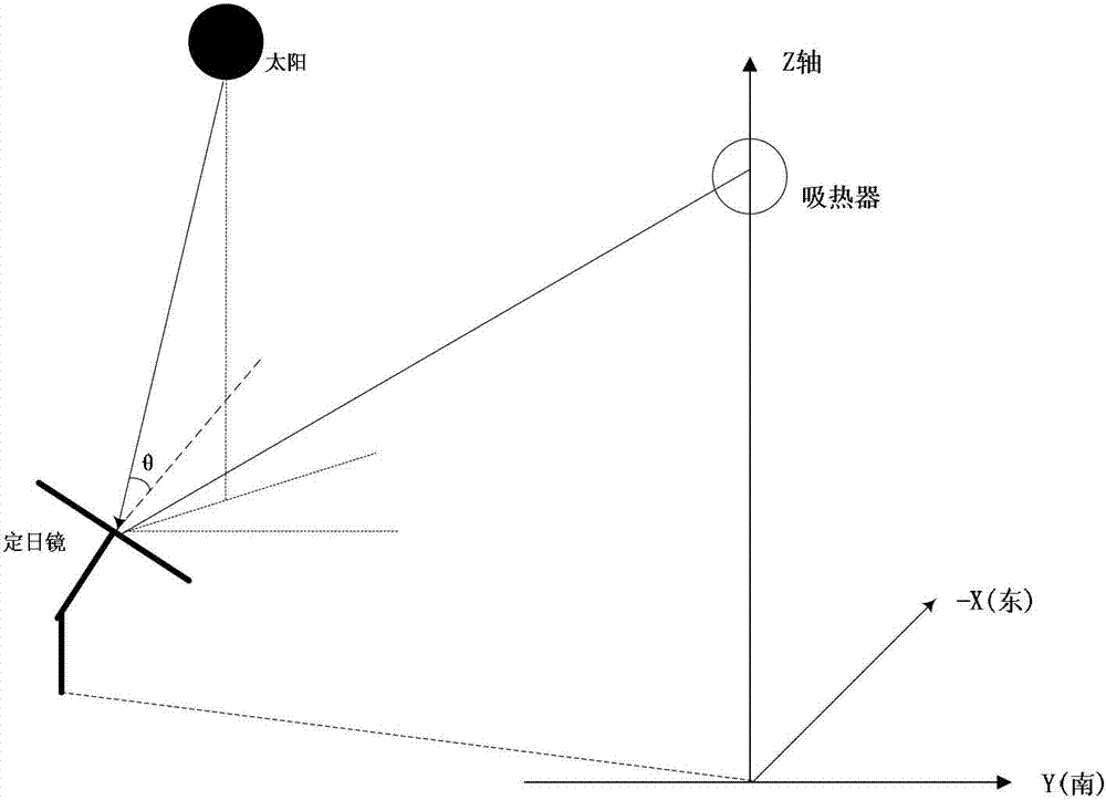
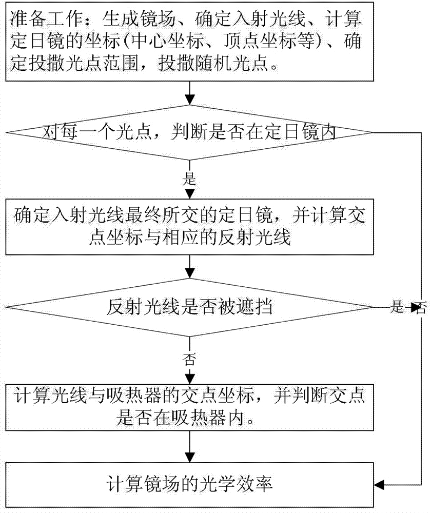
[0094] Such as image 3 As shown, the implementation steps of the calculation method for the optical efficiency of the mirror field of the tower solar thermoelectric system in this embodiment are as follows:

[0095] 1) Generate a mirror field and determine the incident light;

[0096] 2) Determine the casting range according to the mirror field, incident light and the coordinates of the heliostat;

[0097] 3) Randomly cast light spots in the heliostat field within the casting range;

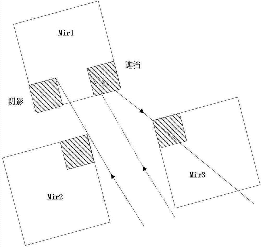
[0098] 4) Use the CUDA computing platform to perform ray tracing for each ray in the form of multi-threading, from the light spots randomly scattered on the ground and the four vertices of the heliostat along the projection coordinates of the incident ray on the ground Determine the intersection of the incident ray and each heliostat. If the projection of the light point is not in any heliostat, the ray corresponding to the light point is an invalid incident ray, and then consider the next lig...


PUM


Abstract

The invention discloses a calculating method of mirror field optical efficiency of a tower type solar thermoelectric system. The method includes the following implementation steps: 1) generating a mirror filed and determining incident light; 2) determining a scattering range according to the mirror field, the incident light and the coordinate of a heliostat; 3) randomly scattering light spots in a heliostat field in the scattering range; 4) utilizing a compute unified device architecture (CUDA) computing platform and adopting multiple threads to conduct light tracing and computing shadow shielding efficiency and overflowing efficiency of the mirror field through the light tracing method; 5) computing cosine efficiency and 6) operating the shadow shielding efficiency, the overflowing efficiency and the cosine efficiency to obtain and output mirror field optical efficiency. The method can utilize high speed operating capability of the CUDA computing platform to achieve graphic processing unit (GPU) high performance parallel operation, enables the multiple threads to conduct computing and judgment simultaneously, and has the advantages of being high in computing efficiency and speed and wide in mirror field application range due to the fact that the whole program costs less time to compute the mirror field efficiency, and optimization and design of the mirror field are benefited.

Description

technical field [0001] The invention relates to the field of tower-type solar thermoelectric systems, in particular to a method for calculating the optical efficiency of a mirror field of a tower-type solar thermoelectric system. Background technique [0002] The tower solar thermoelectric system is a large-scale large-scale concentrating power generation method. The tower solar thermoelectric system is mainly composed of heliostats, towers, heat absorbers, heat exchange devices, heat storage devices and thermal power generation devices. Its work The principle is to use a certain number of heliostats to gather sunlight to the heat absorber on the top of the tower to generate high temperature, then heat the medium flowing through the heat absorber, and generate high-temperature steam to drive the steam turbine to generate electricity. Due to the advantages of large concentration ratio (generally up to 300~1500) and high operating temperature (up to 500°C~1500°C), the tower so...

Claims


Application Information

Patent Timeline
IPC IPC(8): G06F19/00
Inventor 赵豫红周艺艺谢飞
Owner ZHEJIANG UNIV
Learn More