Anatomical knee joint tibial plateau pad with retained posterior cruciate ligaments

A tibial platform and cruciate ligament technology, applied in the field of artificial joints, can solve the problems of prosthesis interference and extrusion on soft tissues, poor proprioception of patients, low patient satisfaction, etc. The effect of risk of failure

Pending Publication Date: 2020-09-15
BEIJING CHUNLIZHENGDA MEDICAL INSTR
View PDF2 Cites 0 Cited by
  • Summary
  • Abstract
  • Description
  • Claims
  • Application Information

AI Technical Summary

Problems solved by technology

[0023] In view of the deficiencies in the prior art, the purpose of the present invention is to overcome the poor matching, poor practicability, low postoperative patient satisfaction, loss of motor function, and interference of the prosthesis to soft tissues caused by the existing symmetrical knee prosthesis. Extrusion and other shortcomings, as well as the existing knee joint prosthesis to overcome the limitations of flexion and extension angle caused by the removal of the posterior cruciate ligament, severe column wear, poor proprioception of the patient, unnatural gait, etc. Anatomical Knee Prosthesis Preserving the Posterior Cruciate Ligament

Method used


Image

  • Anatomical knee joint tibial plateau pad with retained posterior cruciate ligaments
  • Anatomical knee joint tibial plateau pad with retained posterior cruciate ligaments
  • Anatomical knee joint tibial plateau pad with retained posterior cruciate ligaments

Examples


Embodiment Construction

[0099] The present invention will be described in further detail below in conjunction with the accompanying drawings.

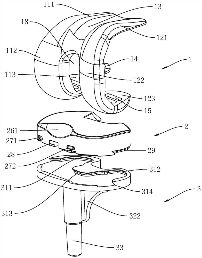
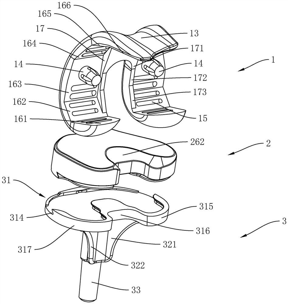
[0100] An anatomical knee joint prosthesis, including femoral condyle 1, tibial plateau pad 2 and tibial plateau rest 3, see figure 2 with image 3 , is the structural diagram of the femoral condyle 1, tibial plateau pad 2 and tibial plateau support 3 when the femur is horizontal, the femoral condyle 1 is a "C" shape with a detachable support 14 in the middle from the side view, and the starting end of the "C" shape The slope of the position is the anterior condyle, and the thickness of the anterior condyle gradually becomes thinner toward the proximal end. The posterior condyle is located at the end of the "C" shape, and the distal end of the femur is located at the opposite side of the "C"-shaped opening. The outer surface of the "C" shape for smooth.

[0101] Viewed from the front, the left side is the medial condyle 11, the right side is the lateral co...


PUM


Abstract

The invention belongs to the technical field of artificial joints, and particularly relates to a knee joint tibial plateau pad with retained posterior cruciate ligaments. The tibial plateau pad is horseshoe-shaped; an inner side condyloid fossa and an outer side condyloid fossa are arranged on the upper surface; and the included angle between the connecting line of the lowest point of the inner side condyloid fossa and the lowest point of the outer side condyloid fossa and the horizontal line is 3 degrees. On the sagittal plane section passing through the inner side condyle fossa, the positionof the inner side condyle fossa is lowest, and the inner side condyle fossa is gradually heightened towards two sides; and on the sagittal plane section passing through the outer side condyle fossa,the middle part protrudes, and two ends separately extend downwards to a vertical outer condyle fossa and a buckling outer fossa and then extend upwards. According to the technical scheme, the gait ofa postoperative patient is more natural, the femoral flexion degree is increased, actions of going upstairs and downstairs, deep squatting, kneeling and the like are better facilitated, and patella snapping and anterior knee pain are reduced.

Description

technical field [0001] The invention belongs to the technical field of artificial joints, in particular to a tibial platform pad of a knee joint with preserved posterior cruciate ligament. Background technique [0002] Concepts and Terminology [0003] In order to correctly describe the shape, position and interrelationship of the human body structure, the present invention uses anatomical posture and orientation terms. [0004] Anatomical posture: body upright, eyes looking straight ahead; feet standing side by side, toes facing forward; upper limbs hanging on both sides of the torso, palms facing forward, thumbs on the outside. [0005] Up and down: head above, feet below. The limbs use proximal and distal to describe the relationship between parts, that is, the root close to the trunk is proximal, and the relatively far or terminal part is distal. [0006] Front and back: The front is the one leaning on the belly of the body, and the back is the one leaning on the back...

Claims


Application Information

Patent Timeline
Patent Type & Authority Applications(China)
IPC IPC(8): A61F2/38
CPCA61F2/389A61F2/3859A61F2/3886A61F2002/30528A61F2002/30476
Inventor 解凤宝史春宝赵永壮
Owner BEIJING CHUNLIZHENGDA MEDICAL INSTR
Why Eureka
Try Eureka