Flatness control device and method for machining flange plate of steel roof beam

A control device and flatness technology, applied in metal processing equipment, manufacturing tools, welding equipment, etc., can solve problems such as high welding stress, low construction efficiency, and potential safety hazards, and achieve reduced application concentration, high application efficiency, and The effect of high construction efficiency

Pending Publication Date: 2020-09-15
JINCHUAN GROUP ENGINEERING AND CONSTRUCTION CO LTD
View PDF0 Cites 2 Cited by
  • Summary
  • Abstract
  • Description
  • Claims
  • Application Information

AI Technical Summary

Problems solved by technology

However, this method has the following disadvantages that are difficult to overcome: the local clamping and fixing method around the flange plate, the force around the flange plate is uneven, the release of welding stress from the surrounding area is greatly affected, and the surrounding deformation of the flange plate after welding Large amount, especially in the middle part of the flange plate, the deformation amount is larger, resulting in too large deviation of the flatness, resulting in a large deviation of the bonding rate of the friction surfaces of the two flange plates, resulting in insufficient bonding rate. To meet the requirements of the design and specifications (fitting rate of 75%), it takes a lot of time and repeated corrections for each truss beam flange plate. The entire operation process is time-consuming and laborious, and the process is cumbersome
Especially for the thick plate flange plates used for large steel roof beam joints, the deviation of flatness caused by welding deformation is relatively large, and its correction is very difficult, and the flatness deviation of the frame structure part formed with the rib plate cannot be corrected to meet the specification The standard requires that only a thin steel sheet should be added between the friction surfaces of the two flange plates during installation, which not only increases the construction cost, affects the construction quality, but also has low construction efficiency and potential safety hazards

Method used


Image

  • Flatness control device and method for machining flange plate of steel roof beam
  • Flatness control device and method for machining flange plate of steel roof beam
  • Flatness control device and method for machining flange plate of steel roof beam

Examples


Embodiment Construction

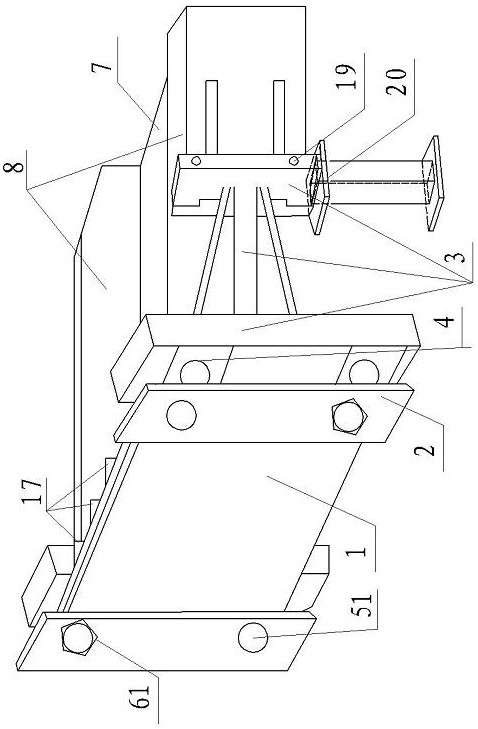
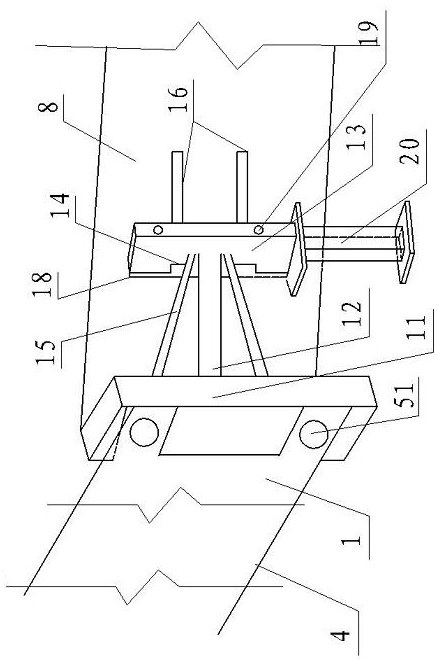
[0031] Such as Figure 1~4 As shown, a flatness control device for processing flange plates of steel roof beams includes a baffle 1 with a square frame 9 around it, and ends perpendicular to the web 7 and flange plate 8 of the H-shaped steel roof beam Welded flange plate 4.

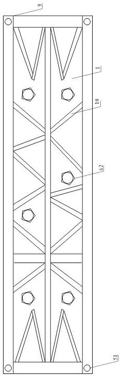
[0032] The two ends of the outer plane of the baffle 1 are provided with square plate cards 2. The plane of the square plate card 2 is provided with machined bolt holes I 51 that match the four corners of the square frame 9; the plane of the baffle 1 is provided with a flange plate 4 A number of matched parallel machining bolt holes Ⅱ52; 16 triangular stiffener plates 10 are provided on the plane of the baffle 1, forming a triangular structure stabilization system; the plane between the flange plate 4 and the web 7 is provided There are ribs 17; two ends of the flange plate 4 are respectively provided with a clamping frame 3.

[0033] The square plate card 2 and the square frame 9 are connected and fixed thr...


PUM


Abstract

The invention relates to a flatness control device for machining a flange plate of a steel roof beam. The flatness control device comprises a baffle and the flange plate, wherein square frames are arranged on the periphery of the baffle, and the flange plate is perpendicularly welded to the ends of a web plate and a flange slab of the H-shaped steel roof beam. Square plate clamps are arranged at the two ends of the outer plane of the baffle, and machining bolt holes I matched with the four corners of the square frames are formed in the planes of the square plate clamps; a plurality of parallelmachining bolt holes II matched with the flange plate are formed in the plane of the baffle, and 16 stiffening plates with triangular structures are arranged on the plane of the baffle; and a rib plate is arranged on a plane between the flange plate and the web plate, and the two ends of the flange plate are each provided with an abutting frame. The invention further discloses a control method for machining the flange plate of the steel roof beam. According to the flatness control device, the flatness control effect on machining the flange plate of the steel roof beam is good, safety and reliability are achieved, operation is convenient and fast, the construction efficiency is high, the application efficiency is higher especially in batch roof beam flange plate construction, and the flatness control method can be popularized and applied to flatness control over machining steel column bottom plates, rib plates and the like.

Description

Technical field [0001] The invention relates to the technical field of steel structure processing, in particular to a flatness control device and method for processing steel roof beam flange plates. Background technique [0002] At present, in the construction of the flange plate of the steel structure roof beam node, the pre-split line positioning is used to partially clamp and fix the distribution plate and the flange plate around the flange plate with a square plug wedge, and the flange plate is welded. Method to prevent large deformation of flange plate welding (control of flatness of flange plate). However, this method has the following disadvantages that are difficult to overcome: the flange plate is partially clamped around the fixing method, the force on the flange plate is uneven, the welding stress is released from the surroundings, and the flange plate is deformed after welding. The amount is large, especially in the middle part of the flange plate, the deformation am...

Claims


Application Information

Patent Timeline
Patent Type & Authority Applications(China)
IPC IPC(8): B23K31/00
CPCB23K31/003
Inventor 程哲李小玲张举胡伟罗永国洪旭张金祝昱
Owner JINCHUAN GROUP ENGINEERING AND CONSTRUCTION CO LTD
Why Eureka
Try Eureka