
Diesel tank winding and welding integrated device

A diesel tank and integrated technology, applied in the field of diesel tank winding and welding integrated device, can solve the problems of time-consuming, cumbersome operation, cumbersome process operation, etc., and achieve the effect of reducing manual operation steps and fast spot welding

Active Publication Date: 2020-09-15
刘海平
View PDF6 Cites 0 Cited by
  • Summary
  • Abstract
  • Description
  • Claims
  • Application Information

AI Technical Summary

Problems solved by technology

[0004] In order to overcome the shortcomings of bending the aluminum alloy sheet of the diesel tank with a bending machine into a rectangular shape, and then using a spot welding machine for spot welding, the process operation is relatively cumbersome, and the two equipments are used together, which is time-consuming and cumbersome. , the technical problem of the present invention is to provide a diesel tank winding and welding integrated device that can be automatically extruded and quickly spot welded

Method used


Image

  • Diesel tank winding and welding integrated device
  • Diesel tank winding and welding integrated device
  • Diesel tank winding and welding integrated device

Examples


Embodiment 1

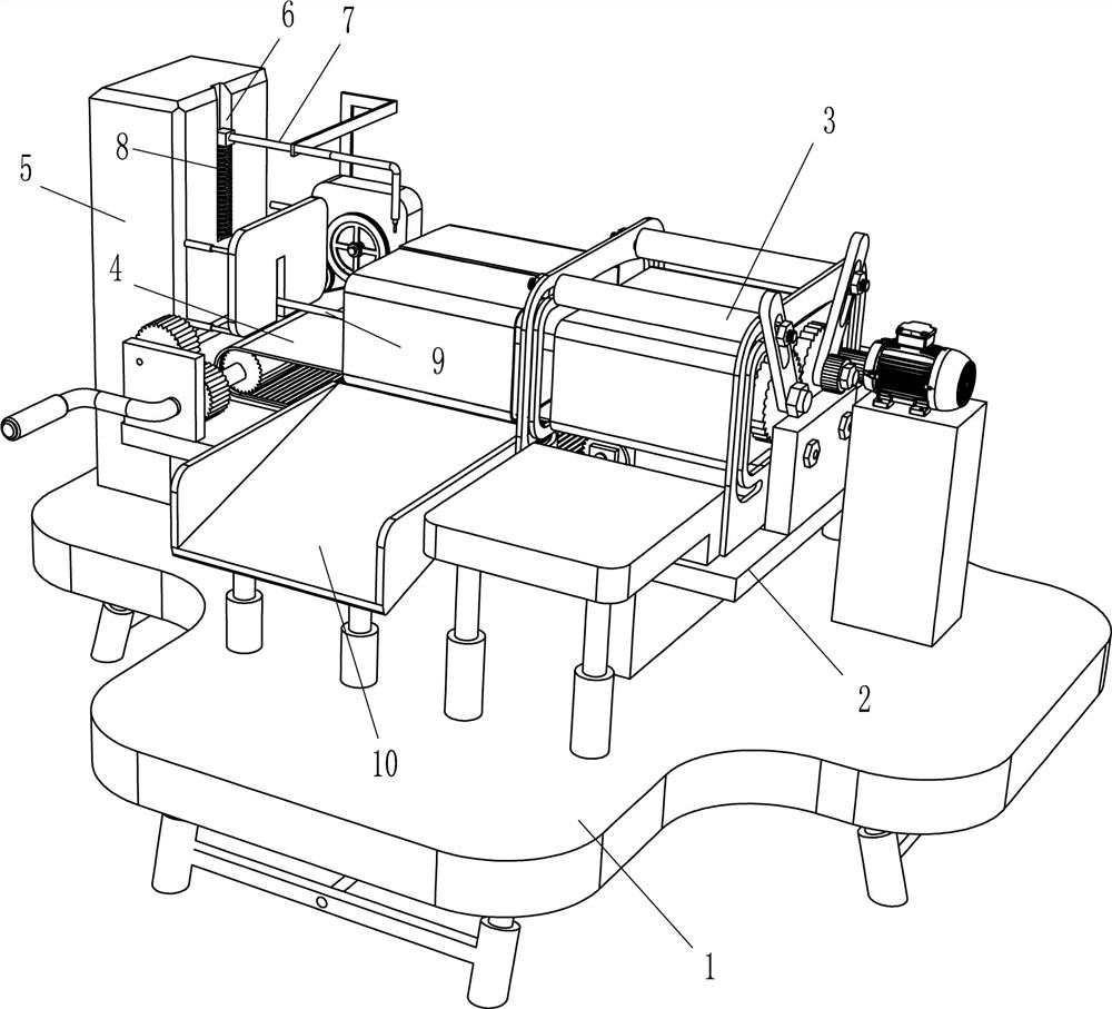
[0023] Such as Figure 1-6 As shown, a diesel tank winding and welding integrated device includes a mounting table 1, a workbench 2, a winding mechanism 3, a transmission mechanism 4, a welding machine 5, a welding device 7, a first elastic member 8, a fixer 9 and Slideway 10, workbench 2 is arranged on the top of installation platform 1, winding mechanism 3 is arranged on the right end of the top of workbench 2, transmission mechanism 4 is arranged on the top of workbench 2, transmission mechanism 4 cooperates with winding mechanism 3, installation platform 1 A welding machine 5 is arranged on the left side of the top, and a sliding groove 6 is provided on the right side of the welding machine 5. The welder 7 of the welding machine 5 can slide up and down in the sliding groove 6, and the welding device 7 and the bottom of the welding machine 5 sliding groove 6 A first elastic member 8 is arranged between them, and the first elastic member 8 is a compression spring. A fixer 9 ...

Embodiment 2

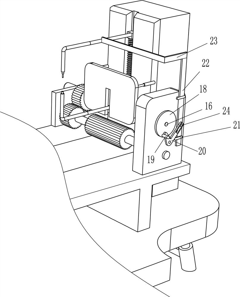
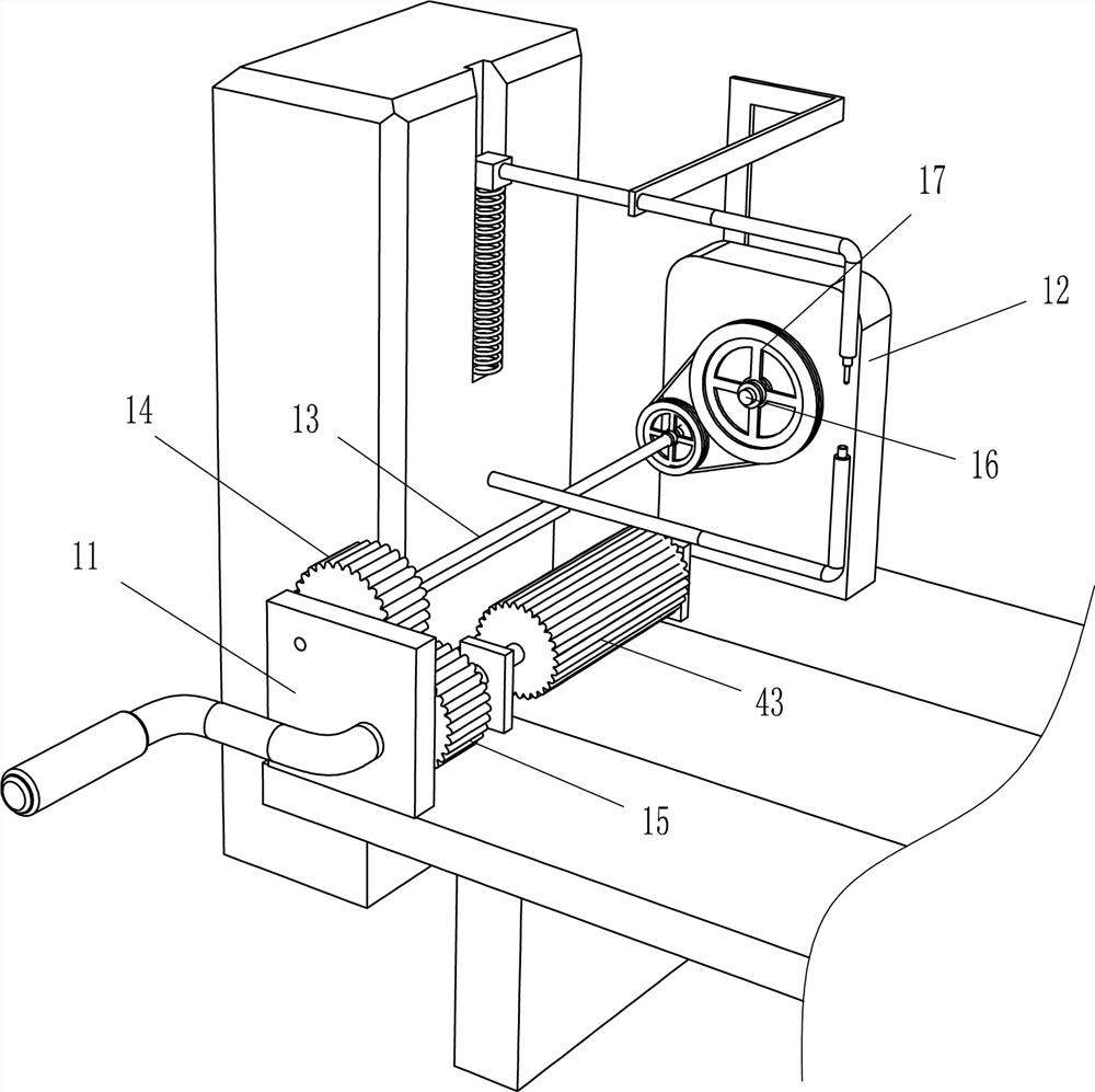
[0028] On the basis of Example 1, such as Figure 1-6 Shown, also comprise first mounting plate 11, second mounting plate 12, rotating shaft 13, the 3rd gear 14, the 4th gear 15, the 3rd rotating shaft 16, belt transmission mechanism 17, disc 18, top shaft 19, L-shaped clamping rod 20, guide sleeve 21, moving plate 22, connecting rod 23 and slide shaft 24, the first mounting plate 11 is arranged on the left front part of the top of the workbench 2, and the rocking bar 45 passes through the first mounting plate 11 to work A second mounting plate 12 is arranged on the left side rear portion of the top of the platform 2, and a rotating shaft 13 is arranged in a rotating manner between the first mounting plate 11 and the second mounting plate 12. The front end of the rotating shaft 13 is provided with a third gear 14, a rocking bar 45 The fourth gear 15 is arranged on the top, the third gear 14 and the fourth gear 15 mesh with each other, the middle part of the second mounting pla...


PUM


Abstract

The invention belongs to the technical field of diesel tank manufacturing, and particularly relates to a diesel tank winding and welding integrated device. The invention aims to provide the diesel tank winding and welding integrated device being capable of carrying out automatic extrusion forming and capable of rapidly carrying out spot welding. According to the technical scheme, the diesel tank winding and welding integrated device comprises a mounting table, a winding mechanism, a transferring mechanism, a welding machine, a welding device and a first elastic piece, wherein a workbench is arranged on the mounting table, and the winding mechanism is arranged at one end of the top of the workbench; the transferring mechanism is arranged on the workbench, and the transferring mechanism is mutually matched with the winding mechanism; and the welding machine is arranged on the side, away from the winding mechanism, of the mounting table, a sliding groove is formed in the side, close to the transferring mechanism, of the welding machine, and the welding device of the welding machine can slide up and down in the sliding groove. The diesel tank winding and welding integrated device achieves the effects of being capable of carrying out automatic extrusion forming and capable of rapidly carrying out spot welding.

Description

technical field [0001] The invention belongs to the technical field of diesel tank production, and in particular relates to a diesel tank winding and welding integrated device. Background technique [0002] Diesel box-type cars are widely used in life, involving all walks of life. The fuel tank is the fuel storage container of the vehicle and is an essential part of the vehicle. The fuel tank can be divided into two types: open fuel tank and closed fuel tank. The fuel tank must have a large enough volume; the oil suction pipe and oil return pipe should be inserted below the minimum liquid level to prevent air suction and return oil from splashing bubbles. Most diesel vehicles now The fuel tank preparations are all welded from aluminum alloy sheets. [0003] At present, the staff need to bend the aluminum alloy sheet used to make the diesel tank into a rectangular shape, then take it out, and take it to the spot welding machine for spot welding at both ends of the folded pa...

Claims


Application Information

Patent Timeline
Patent Type & Authority Applications(China)
IPC IPC(8): B23P23/00
CPCB23P23/00
Inventor 刘海平
Owner 刘海平
Learn More