
Stranded wire contact pin cutting and spot welding device

A pin and stranded wire technology, which is applied in the field of stranded wire pin cutting and spot welding devices, can solve the problems of unguaranteed, poor spot welding consistency, and low efficiency of stranded wire pin spot welding, so as to improve welding quality and improve Production efficiency, the effect of ensuring continuous feeding

Pending Publication Date: 2022-07-29
杭州航天电子技术有限公司
View PDF6 Cites 0 Cited by
  • Summary
  • Abstract
  • Description
  • Claims
  • Application Information

AI Technical Summary

Problems solved by technology

[0003] Twisted wire pins, the key components in the micro-rectangular connector, are particularly important. The quality of the stranded wire pins directly affects the performance of the micro-rectangular connector, and the spot welding of both ends of the stranded wire pins is an important process. The fullness of the solder joints of the wire pins, whether there is a virtual weld or the solder joints are not centered will directly affect the product quality of the stranded wire pins. The traditional production of the stranded wire pins is all manual work. First, the stranded wire pins are manually cut. , and then pick the stranded wire pins one by one with tweezers and place them on the tooling, and then put the tooling into the laser spot welding machine for laser spot welding. The existing spot welding at both ends of the stranded wire pins has the following deficiencies : (1) The consistency of spot welding is poor and cannot be guaranteed. Since each is manually spot welded, and because the tooling has a certain gap, it cannot be guaranteed that each solder joint is in the exact center; (2) Stranded wire pins Spot welding efficiency is low, one person can only produce 2,000 stranded wire pins for spot welding at both ends per day

Method used


Image

  • Stranded wire contact pin cutting and spot welding device
  • Stranded wire contact pin cutting and spot welding device
  • Stranded wire contact pin cutting and spot welding device

Examples


Embodiment Construction

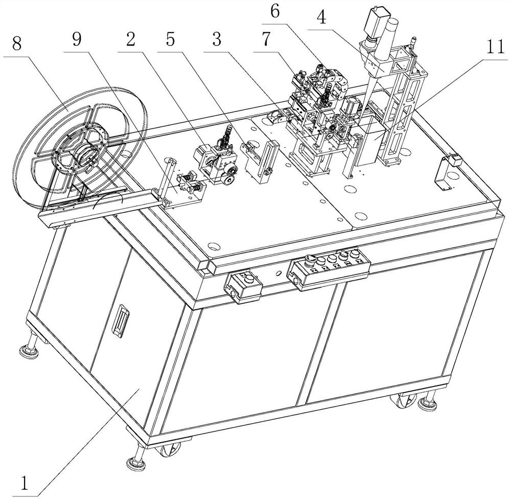
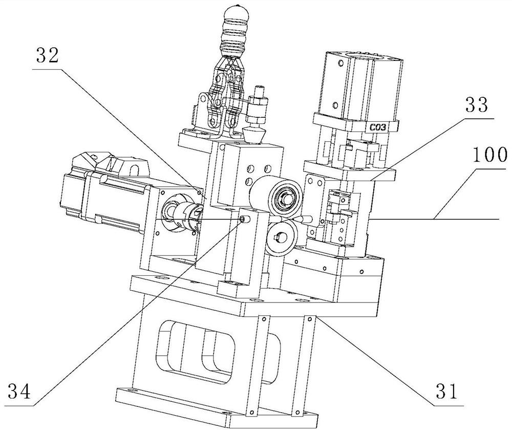
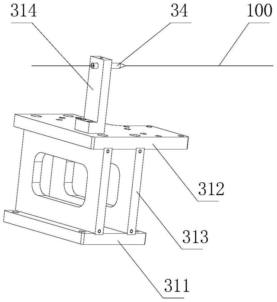
[0037] like figure 1 , figure 2 , image 3 , Figure 4 , Figure 5 , Image 6 , Figure 7 , Figure 8 , Figure 9 , Figure 10 , Figure 11 , Figure 12 , Figure 13 , Figure 14 , Figure 15 and Figure 16 As shown, a stranded wire pin cutting spot welding device includes a frame 1, a feeding module 2, a cutting module 3 and a welding module 4. The feeding module 2, the cutting module 3 and the welding module 4 are all arranged in On the rack 1, the rack 1 is provided with a material shortage sensing module 5, a handling module 6 and a stranded wire pin sensing fiber optic module 7, and the material shortage sensing module 5 is arranged between the feeding module 2 and the cutting module 3. The module 6 is arranged between the cutting module 3 and the welding module 4, the stranded wire pin sensing fiber module 7 is arranged between the handling module 6 and the welding module 4, and the handling module 6 includes a moving mechanism 61 and a rotating clamping m...


PUM


Abstract

The invention relates to a stranded wire contact pin cutting and spot welding device which comprises a rack, a feeding module, a cutting module and a welding module, a carrying module and a stranded wire contact pin sensing optical fiber module are arranged on the rack, the carrying module is arranged between the cutting module and the welding module, and the carrying module comprises a moving mechanism and a rotary clamping mechanism. The stranded wire pin wire cut by the cutting module is clamped by the rotary clamping mechanism and then moved to the position below the welding module through the moving mechanism, and spot welding of the two ends of the stranded wire pin wire is achieved through rotation of the rotary clamping mechanism during welding; the device has the advantages that the stranded wire contact pin wire is fed into the cutting module through the feeding module to be cut, and the carrying module is arranged between the cutting module and the welding module, so that the stranded wire contact pin wire cut by the cutting module can be sent out from the cutting module, the welding process and the cutting process form two mutually independent processes, and the welding efficiency is improved. And the two are not interfered, so that the overall production efficiency is improved.

Description

technical field [0001] The invention relates to a cutting and spot welding device for stranded wire pins. Background technique [0002] In recent years, with the rapid development of the aerospace field and the electronics industry, the number of connectors in the aerospace field has grown rapidly, and the quality requirements have become higher and higher, which requires connector manufacturers to improve production efficiency and product quality. , Because the product size of traditional connectors is too large, the latest aerospace-grade micro-rectangular connectors are favored by aerospace products due to their light weight and low volume, and stranded pins are the most critical in micro-rectangular connectors. Components. [0003] The key components of the micro-rectangular connector are stranded pins. The quality of the stranded pins directly affects the performance of the micro-rectangular connector. The spot welding of both ends of the stranded pins is an important ...

Claims


Application Information

Patent Timeline
Patent Type & Authority Applications(China)
IPC IPC(8): H01R43/16H01R43/02
CPCH01R43/16H01R43/02
Inventor 李栋韩冬伟胡建明罗理想秦野秋
Owner 杭州航天电子技术有限公司
Learn More