Multi-wedge-belt cutter

A multi-ribbed belt and cutting machine technology, applied in metal processing and other directions, can solve the problems of less wedge or half wedge, multi-ribbed belt scrap, multi-ribbed and other problems, and achieve the effect of reducing the scrap rate

Pending Publication Date: 2020-09-15
GATES UNITTA POWER TRANSMISSION (SUZHOU) LIMITED
View PDF1 Cites 1 Cited by
  • Summary
  • Abstract
  • Description
  • Claims
  • Application Information

AI Technical Summary

Problems solved by technology

[0003] During the cutting process of the molded V-ribbed belt, it is often necessary to tension and fix the rubber sleeve first. The current cutting method is that the wedge of the rubber sleeve is everted, and the entire rubber sleeve is placed on the cutting shaft, and then the cutting shaft expands and tensions the rubber sleeve. Then adopt a guide roller with the outer surface fully covered with teeth, the teeth on the guide roller are formed by protrusions and grooves, the wedges of the rubber sleeve correspond to the grooves of the guide roller or the wedge grooves of the rubber sleeve correspond to the protrusions of the guide roller, the guide rollers The roller presses the rubber sleeve to the support roller, so that the support roller and the guide roller clamp the rubber sleeve to fix the rubber sleeve. At the same time, when the rubber sleeve rotates, the protrusions or grooves on the guide roller engage with the grooves or wedges on the rubber sleeve. , and then move the tool to cut along the wedge groove according to the predetermined width. However, in practical applications, it is found that the multi-ribbed belt often appears multi-ribbed, less-ribbed or half-ribbed, which causes the multi-ribbed belt to be scrapped. It is urgent to provide a technology to solve this problem. kind of problem

Method used


Image

  • Multi-wedge-belt cutter
  • Multi-wedge-belt cutter
  • Multi-wedge-belt cutter

Examples


Embodiment Construction

[0022] The present invention will be described in detail below with reference to the accompanying drawings.

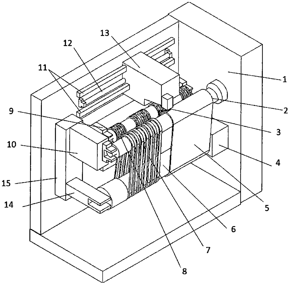
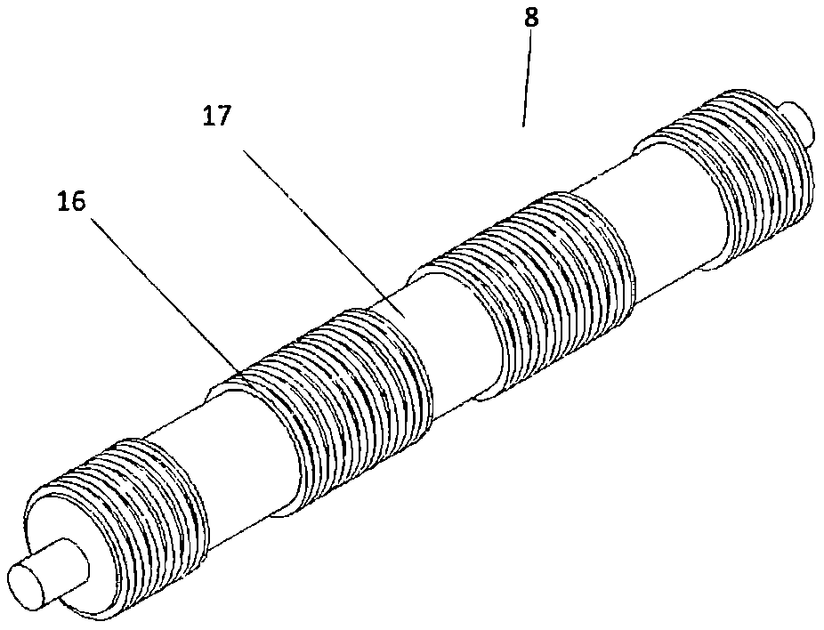
[0023] figure 1 It is a schematic diagram of the structure of the V-ribbed belt cutting machine. The V-ribbed belt cutting machine includes a fixed bracket 1. The fixed bracket 1 has a base and two sides. One end of the supporting roller 2 is installed on one side of the fixed bracket 1, and the other end is suspended. It is convenient to put the rubber sleeve 5 on it, the tension roller 6, the guide roller 8 are arranged parallel to the axis of the support roller 2, the end of the tension roller 6 close to the fixed end of the support roller is connected with the tension device 4, and the other end is the same as the support roller 2 The mode is suspended, and is convenient to adorn rubber sleeve 5. The tensioning device 4 is connected to the fixed bracket 1 in a movable manner, and the movement of the tensioning device 4 can be a rotary motion, and the tensioning ro...


PUM


Abstract

The invention provides a multi-wedge-belt cutter which comprises a fixed support, a support roller, a guide roller, a cutter, a tension roller, and a drive device and a tension device arranged on thefixed support. One end of the support roller is arranged on the fixed support; the guide roller, the tension roller and the support roller are arranged in parallel in the axial direction; the drive device is connected with the guide roller so as to drive the guide roller to move in the direction perpendicular to the axis of the support roller; the tension device is connected with one end of the tension roller so as to drive the tension roller to move in the direction perpendicular to the axis of the support roller; the tension roller can rotate relative to the tension device; and teeth segmentally distributed in the axis direction of the guide roller are arranged on the outer circumference face of the guide roller. The occurrence of the phenomenon of more wedges, less wedges or semi-wedgesduring multi-wedge-belt cutting is reduced.

Description

technical field [0001] The invention relates to a V-ribbed belt cutting machine, in particular to a cutting machine for molding a V-ribbed belt. Background technique [0002] Molded V-ribbed belt is a kind of wedge or rib formed on the surface of V-ribbed belt through tooth-shaped extrusion inside the mold, without grinding, which reduces the dust in the workshop and reduces the generation of waste. The production method widely used in 2014, the specific molding process can be seen in the patent document with the announcement date of the United States on January 21, 2014 and the announcement number US8632650B2. Whether the surface of the wedge belt is covered with fabric, the molded rubber sleeve already has a formed wedge on the surface, because the rubber sleeve is wide, the rubber sleeve with wedge needs to be cut according to the required number of wedges or width, such as 3PK, 4PK, 5PK and other V-ribbed belts with different widths, and then form a single V-ribbed belt...

Claims


Application Information

Patent Timeline
IPC IPC(8): B26F1/38B26F1/44B26D7/06
CPCB26D7/06B26F1/3866B26F1/44
Inventor 时宁宁闫军顾亮峰郭伟赵洋
Owner GATES UNITTA POWER TRANSMISSION (SUZHOU) LIMITED
Why Eureka
Try Eureka