Movable new energy automobile charging pile

A technology of new energy vehicles and charging piles, which is applied in the direction of electric vehicle charging technology, electric vehicles, charging stations, etc., can solve the problems of garbage brought into the charging tank, shorten the service life, and make it difficult to move quickly, so as to increase the shielding area and reduce the Risk of damage, effect of improving service life

Active Publication Date: 2020-09-15
SOUTHWEST UNIVERSITY FOR NATIONALITIES
View PDF6 Cites 1 Cited by
  • Summary
  • Abstract
  • Description
  • Claims
  • Application Information

AI Technical Summary

Problems solved by technology

[0003] At present, the development of charging piles is not very mature, and there are often some unavoidable problems in actual use. The first is that they are difficult to move quickly, which makes them unable to be flexibly arranged at various points of use. At the same time, in use, the surface of the plug It is often contaminated with dust and other garbage. Inserting a charging pile for charging will bring garbage into the charging slot of the charging pile, reducing its service life

Method used


Image

  • Movable new energy automobile charging pile
  • Movable new energy automobile charging pile
  • Movable new energy automobile charging pile

Examples


Embodiment 1

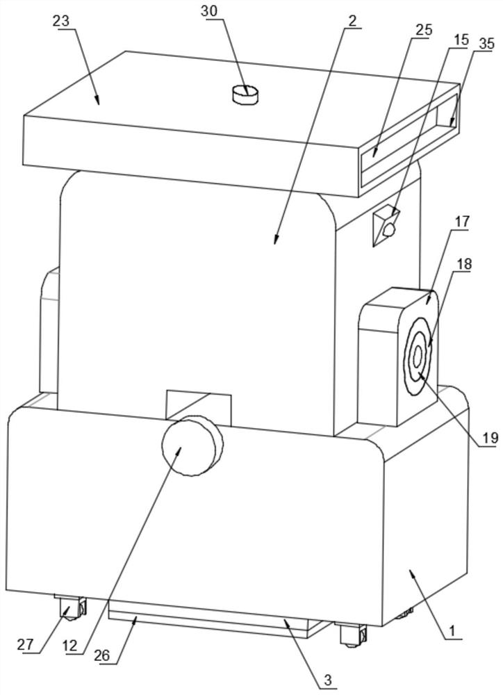
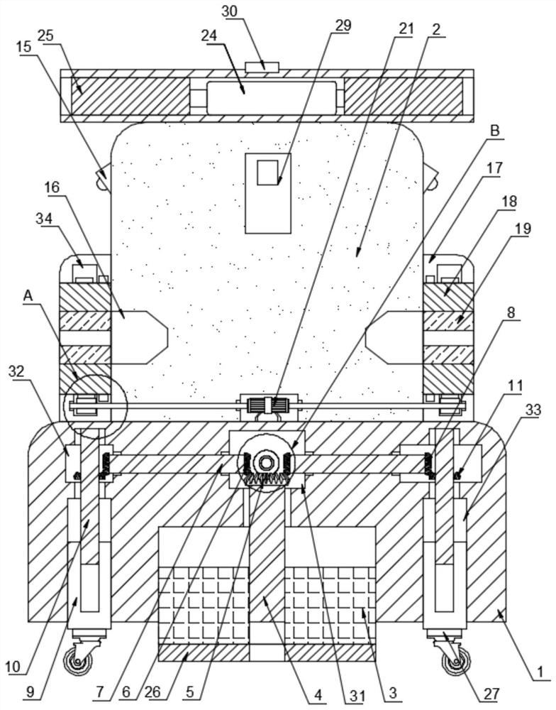
[0033] see figure 1 , figure 2 , Figure 4 and Figure 5 As shown, a movable new energy vehicle charging pile of the present invention includes a base 1 and a charging pile main body 2, the charging pile main body 2 is fixedly connected to the top of the base 1, and a moving mechanism is provided inside the base 1;

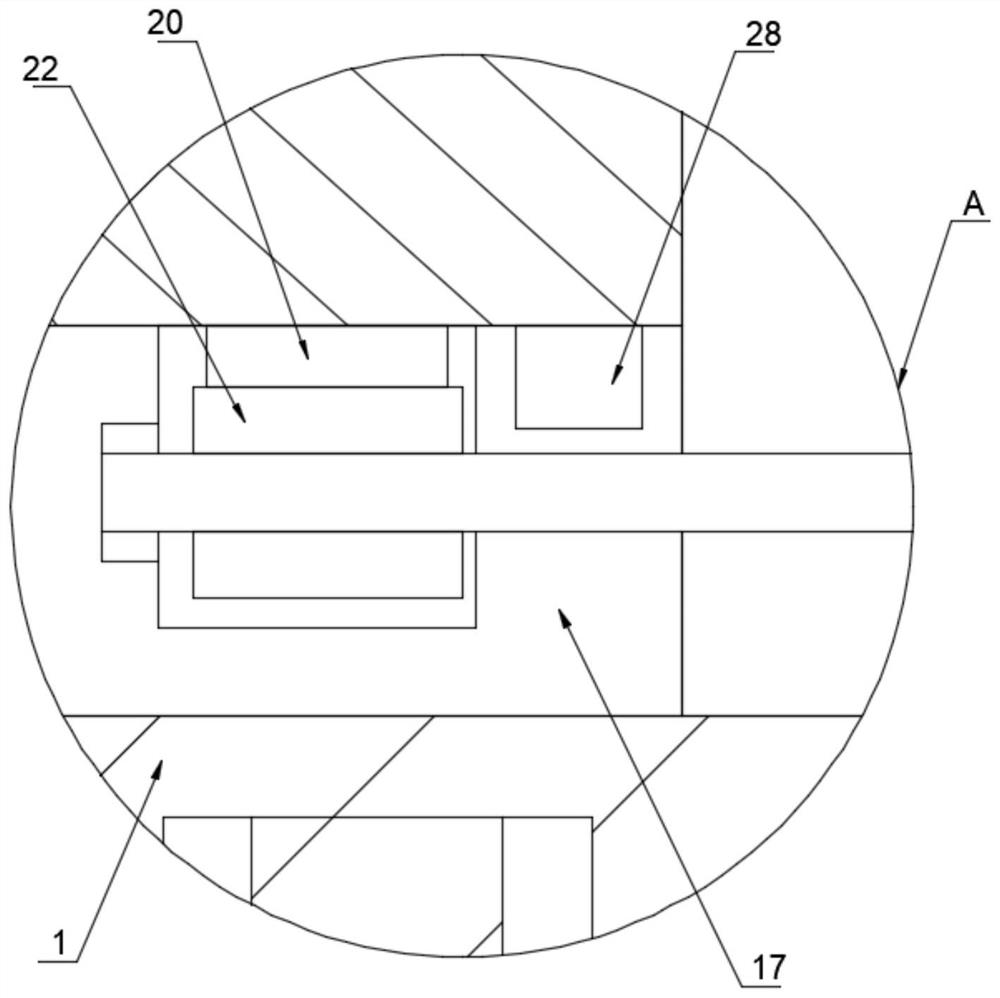
[0034]The moving mechanism includes a support seat 3, which is embedded in the bottom of the base 1, and a first cavity 31 is opened inside the base 1, and the first cavity 31 is located at the top of the support seat 3, and the support A first threaded rod 4 is sleeved inside the seat 3, and the top end of the first threaded rod 4 extends to the inside of the first cavity 31, and the first threaded rod 4 is threadedly connected with the support seat 3, and the first threaded rod 4 The top end is fixedly connected with a first bevel gear 5, and both sides of the first bevel gear 5 are provided with a second bevel gear 6, and the second bevel gear 6 is engaged ...

Embodiment 2

[0040] see Figure 1-3 and Figure 6 As shown, a movable new energy vehicle charging pile of the present invention also includes a cleaning mechanism and a rainproof mechanism, the cleaning mechanism is located outside the main body 2 of the charging pile, and the rainproof mechanism is located on the top of the main body 2 of the charging pile;

[0041] The cleaning mechanism includes two infrared sensors 15. The infrared sensor is a sensor capable of sensing the infrared rays radiated by the target and using the physical properties of the infrared rays for measurement. According to the detection mechanism, it can be divided into photon detectors and thermal detectors. The model of the infrared sensor 15 is LHI954. A charging slot 16 is provided, and side plates 17 are fixedly connected to both sides of the main body of the charging pile 2. The two side plates 17 are respectively located at the bottom of the two infrared sensors 15, and the two side plates 17 are respectivel...


PUM


Abstract

The invention discloses a movable new energy automobile charging pile which comprises a base and a charging pile main body. The charging pile main body is fixedly connected to a top of the base, a moving mechanism is arranged in the base, a cleaning mechanism is arranged on an outer side of the charging pile main body, and a rainproof mechanism is arranged at the top of the charging pile main body. And the moving mechanism comprises a supporting seat, the supporting seat is embedded in the bottom of the base, a first cavity is arranged in the base, and the first cavity is located in the top ofthe supporting seat. In the invention, the moving mechanism is arranged; during stable placement, stable support can be performed through the supporting seat; and when moving is needed, rotating wheels can be rotated so that a trundle stretches out, the supporting seat retracts, original supporting seat supporting is converted into trundle supporting, the charging pile can be conveniently and rapidly moved, the rotating wheels can be rotated reversely after moving, the trundle retracts again, the supporting seat stretches out again and is converted into supporting seat supporting again, and stable supporting of the charging pile is continuously achieved through the supporting seat.

Description

technical field [0001] The technical field of the charging pile of the present invention particularly relates to a movable charging pile for new energy vehicles. Background technique [0002] The function of the charging pile is similar to the refueling machine in the gas station. It can be fixed on the ground or wall, and installed in public buildings (public buildings, shopping malls, public parking lots, etc.) and residential area parking lots or charging stations. Charge all models of electric vehicles. The input end of the charging pile is directly connected to the AC grid, and the output end is equipped with a charging plug for charging the electric vehicle. Charging piles generally provide two charging methods: conventional charging and fast charging. People can use a specific charging card to swipe the card on the human-computer interaction interface provided by the charging pile to perform corresponding charging methods, charging time, and cost data printing. The ...

Claims


Application Information

Patent Timeline
Patent Type & Authority Applications(China)
IPC IPC(8): B60L53/31F16M3/00B60L53/30B08B1/00B08B1/04
CPCB08B1/002B08B1/04B60L53/30B60L53/31F16M3/00Y02T10/70Y02T10/7072Y02T90/12
Inventor 邓彦松刘兴文
Owner SOUTHWEST UNIVERSITY FOR NATIONALITIES
Why Eureka
Try Eureka