A car front suspension structure
A technology for automobiles and subframes, which is applied to vehicle components, substructures, power units, etc., can solve the problems of inability to precisely control the connection strength of connecting blocks and reinforcement brackets, inability to ensure engine stress conditions, and engine intrusion into the cab, etc. To achieve the effect of easier quality assurance, avoid unnecessary separation, and controllable safety performance
- Summary
- Abstract
- Description
- Claims
- Application Information
AI Technical Summary
Problems solved by technology
Method used
Image
Examples
Embodiment 1
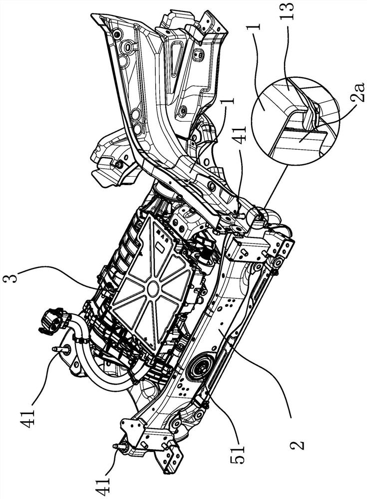
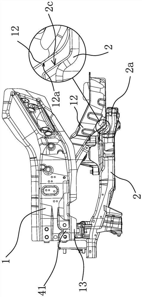
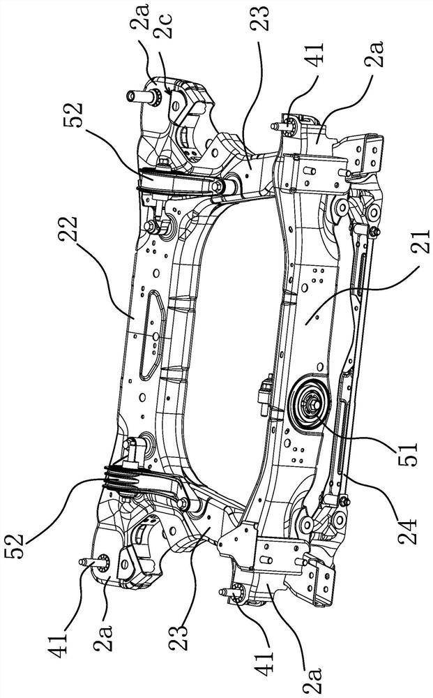
[0038] Such as figure 1 As shown, a kind of automobile front suspension frame, there are two vehicle body longitudinal beams 1 arranged at intervals in the engine compartment in front of the automobile cab, and the front suspension structure includes subframe 2 and power assembly 3, wherein, vehicle body longitudinal beam 1 Both the subframe and the subframe 2 are made of materials with high structural strength and are not easily deformed. The subframe 2 adopts a square frame structure. The powertrain 3 can be an engine or a motor. The suspension structure arranged at three circumferential intervals is connected to the subframe 2, so that the powertrain 3 is only supported by the subframe 2 and forms an integral body with the subframe 2, and the engine is located in the longitudinal direction of the two bodies. Between the beams 1, the subframe 2 is only connected to the two body longitudinal beams 1 through several vertically arranged connecting bolts 41, the material strengt...
Embodiment 2
[0050] The technical solution of this embodiment is basically the same as that of Embodiment 1, the difference is that in this embodiment, the connecting bolt 41 does not use the inner sleeve 42, but the connecting bolt 41 is directly inserted into the mounting hole 2b and Cooperate with the installation hole 2b, of course, when adopting this solution, the material requirements for the suspension part 2a are higher, and the structural strength at the installation hole 2b of the suspension part 2a must be ensured.
Embodiment 3
[0052] Such as Figure 6 As shown, the technical solution of this embodiment is basically the same as that of Embodiment 1. The difference is that in this embodiment, the end of the inner sleeve 42 facing the installation hole 1a and protruding from the end of the installation hole 2b has an annular protrusion. Along 42b, the outer diameter of the annular convex edge 42b is larger than the diameter of the installation hole 2b, which makes the installation and positioning of the inner sleeve 42 more convenient. Moreover, in this embodiment, the screw body is provided with a fracture guide groove 41a along the circumferential direction, and the fracture guide groove 41a is located between the inner sleeve 42 and the screw sleeve 43. In this way, the strength of the screw body where the fracture guide groove 41a is set is relatively lower. Make the screw body easier to break at this place. Of course, the fracture guide groove 41a is not easy to be set too deep, so that the screw...
PUM
 Abstract
Description
Claims
Application Information
 - R&D Engineer
- R&D Manager
- IP Professional
- Industry Leading Data Capabilities
- Powerful AI technology
- Patent DNA Extraction
Browse by: Latest US Patents, China's latest patents, Technical Efficacy Thesaurus, Application Domain, Technology Topic, Popular Technical Reports.
© 2024 PatSnap. All rights reserved.Legal|Privacy policy|Modern Slavery Act Transparency Statement|Sitemap|About US| Contact US: help@patsnap.com


