Connecting device suitable for turnover bracket assembly
A connecting device and flipping bracket technology, which is applied in the direction of transportation and packaging, the upper structure of the truck, the upper structure, etc., can solve the problems of low difficulty in tightening the connecting bolts and high difficulty in tightening the connecting bolts, and achieve good assembly effect and difficulty in tightening Low, the effect of reducing the difficulty of tightening
- Summary
- Abstract
- Description
- Claims
- Application Information
AI Technical Summary
Problems solved by technology
Method used
Image

Examples
Embodiment 1
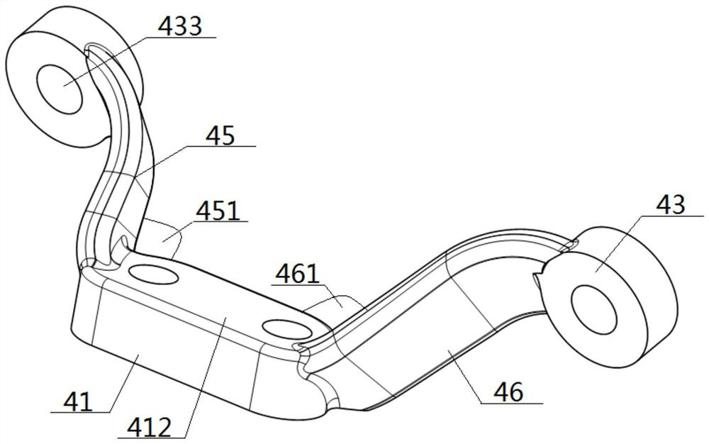
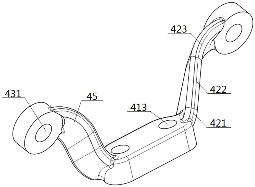
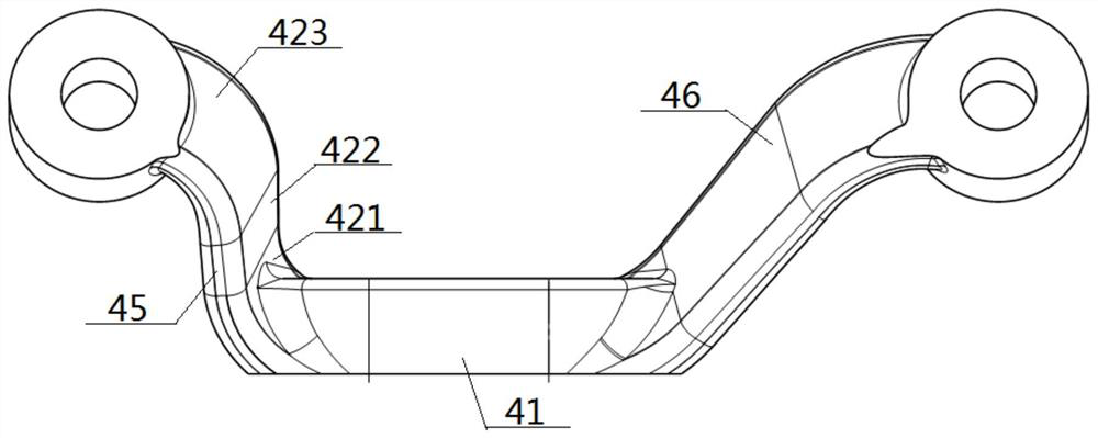
[0048] see figure 1 — Figure 10 , a connecting device suitable for flipping the bracket assembly, including an upper connecting piece 4, the upper connecting piece 4 includes a connecting middle plate 41 and connecting wing plates 42 connected to its two ends, and the ends of the connecting middle plate 41 It is connected with the bottom end of the connecting wing plate 42, and the top end of the connecting wing plate 42 extends upwards. The top end of the connecting wing plate 42 is provided with a wing connecting hole 431 connected with the cab 8. The hole surface 433 of the wing connecting hole 431 is On the horizontal plane, the hole surface 433 intersects the plate surface 412 connecting the middle plate 41 . The top of the connecting wing plate 42 is connected to the side of the flat connecting platform 43, and the middle part of the flat connecting platform 43 is provided with a through wing connecting hole 431. The top surface of the flat connecting platform 43 is a ...
Embodiment 2
[0050] Basic content is the same as embodiment 1, the difference is:
[0051] The connecting wing 42 is a No. 1 sub-wing 45 and a No. 2 sub-wing 46. The bottom of the No. 1 sub-wing 45 is connected to the left end of the connecting middle plate 41, and the bottom of the No. 2 sub-wing 46 is End is connected with the right end of connecting middle plate 41, and the length of No. 2 sub-wing board 46 is greater than the length of No. 1 sub-wing board 45. The connection structure between the No. 1 sub-wing 45 and the connecting middle plate 41, and the connection structure between the No. 2 sub-wing 46 and the connecting middle plate 41 are obliquely handed over. The included angle 451 of the No. 1 wing between the No. 1 sub-wing 45 and the connecting middle plate 41 is an obtuse angle, and the No. 2 wing between the No. 2 sub-wing 46 and the connecting mid-plate 41 is obtuse. The included angle 461 is an obtuse angle, and the included angle 461 in the second wing is larger than ...
Embodiment 3
[0053] Basic content is the same as embodiment 1, the difference is:
[0054] The connection device also includes a lower turning member 3, which includes an outer connecting portion 5 and an inner connecting portion 6, and the middle part of the outer connecting portion 5 is provided with a shaft passing hole 51 for the turning shaft 1 to pass through. , the right side part of the external connection part 5 is connected with the left side part of the internal connection part 6, the top surface of the internal connection part 6 is connected with the cab 8, and the top of the external connection part 5 is provided with a concave snap-in mechanism 7 The clamping mechanism 7 includes a No. 1 inclined plane 710 and a No. 2 inclined plane 720. The distance between the top of the No. 1 inclined plane 710 and the No. 2 inclined plane 720 is greater than the distance between the bottoms. , the angle 44 formed between the connecting wing plate 42 and the first inclined plane 710 is an ...
PUM
 Abstract
Description
Claims
Application Information
 - R&D
- Intellectual Property
- Life Sciences
- Materials
- Tech Scout
- Unparalleled Data Quality
- Higher Quality Content
- 60% Fewer Hallucinations
Browse by: Latest US Patents, China's latest patents, Technical Efficacy Thesaurus, Application Domain, Technology Topic, Popular Technical Reports.
© 2025 PatSnap. All rights reserved.Legal|Privacy policy|Modern Slavery Act Transparency Statement|Sitemap|About US| Contact US: help@patsnap.com