
Lock of speed reduction device with clutch mechanism

A technology of clutch mechanism and deceleration device, which is applied to non-mechanical transmission-operated locks, building locks, building structures, etc., can solve the problems of small output torque, potential safety hazards, and large energy consumption, and achieve high power transmission efficiency and power consumption. The conduction direction is consistent and the effect of meeting practical requirements

Pending Publication Date: 2020-09-15
浙江莱优科技有限公司
View PDF0 Cites 0 Cited by
  • Summary
  • Abstract
  • Description
  • Claims
  • Application Information

AI Technical Summary

Problems solved by technology

At present, the clutch technology of fully automatic lock body includes two directions of manual clutch and automatic clutch. Manual clutch refers to the external force generated manually to disengage the power gear from the clutch. When the friction force is applied, the load rotates with the electric motor. When the manual force is greater than the friction force, the load rotates with the manual force. The torque output in this way is restricted by the friction force. In practical applications, other technical means should be given to reduce the manual force; automatic clutch Another way is to use the balance wheel technology, that is, a balance wheel is set in the reduction mechanism. When the electric power is driven, the balance wheel turns to the next gear under inertia and combines with it to output power. When the electric power disappears, the balance wheel loses its inertial force and There is a problem in this method, that is, when the electric force drives the load to rotate to the limit of the load position and cannot be reversed, the balance wheel and the gear of the next stage are in a state of engagement. At this time, if the motor is damaged, it cannot If it is rotated, manual power and automatic power cannot achieve clutching. This problem is a serious safety hazard.
Therefore, comparing the two technical characteristics of manual and automatic, manual is the most reliable way. There is only one design problem, that is, the choice of power and the design of the reducer must meet the assembly requirements of the lock body space. In order to reduce the power and deceleration Due to the volume of the gear, the current design scheme mainly adopts the worm gear reduction mechanism or the planetary reducer with bevel gears, etc. The main problems of these two forms are low efficiency, small output torque, or high energy consumption under the same output torque question

Method used


Image

  • Lock of speed reduction device with clutch mechanism
  • Lock of speed reduction device with clutch mechanism
  • Lock of speed reduction device with clutch mechanism

Examples


Embodiment

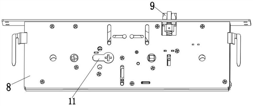
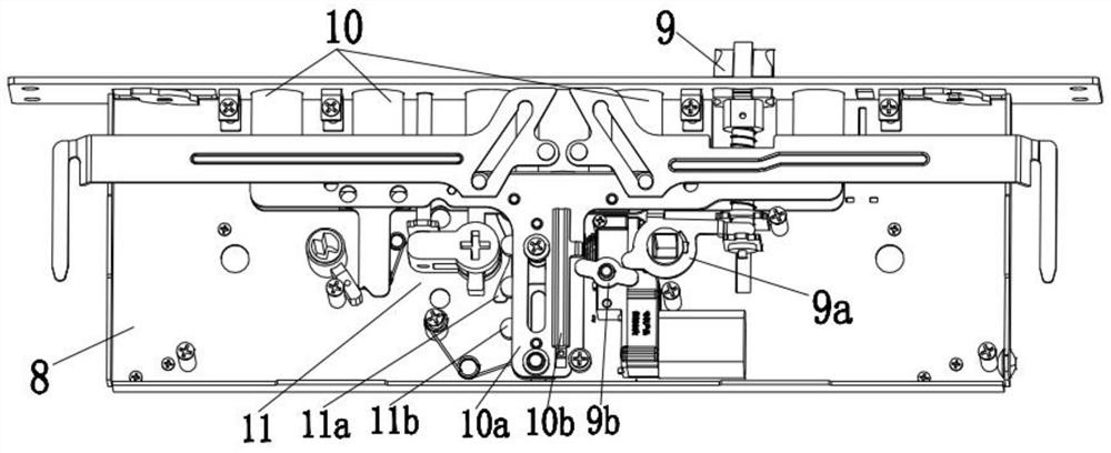
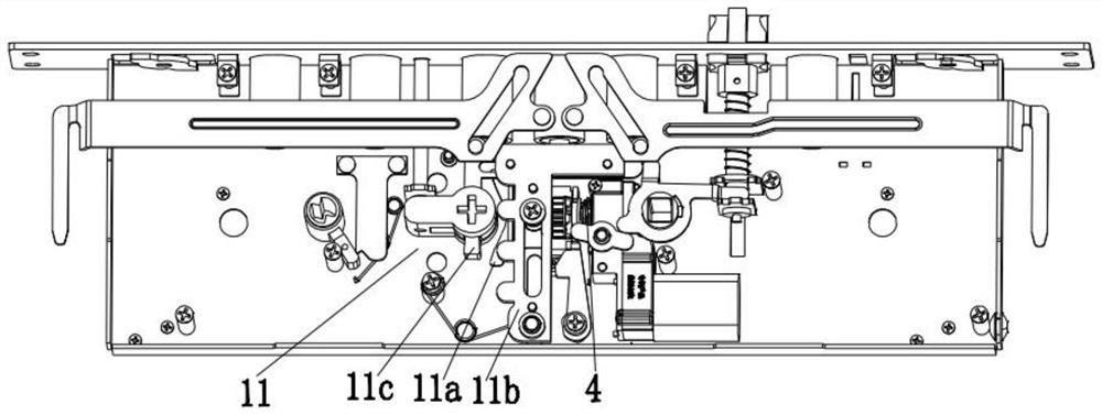
[0032] Such as Figure 1-8 As shown, a lockset with a deceleration device with a clutch mechanism includes a lock body 8, a main dead bolt 9, an auxiliary dead bolt 10, a key drive mechanism 11 and a deceleration device with a clutch mechanism, the main dead bolt 9, the auxiliary lock Tongue 10, key drive mechanism 11 and deceleration device with clutch mechanism are all arranged on the lock body 8;

[0033] The reduction device with a clutch mechanism includes a reduction box 5, a reduction gear set 6, a driving motor 7 and a clutch mechanism. box 5, and the output end of the drive motor 7 is connected to the clutch mechanism through the reduction gear set 6;

[0034] The auxiliary bolt 10 and the key driving mechanism 11 are drivingly connected to the clutch mechanism, and the auxiliary bolt 10 is drivingly connected to the main bolt 9 .

[0035] Preferably, the clutch mechanism includes a clutch shaft 1, an output gear 2, a clutch ring 3 and a clutch spring 4;

[0036] D...


PUM


Abstract

The invention relates to a lock of a speed reduction device with a clutch mechanism. The lock comprises a lock body, a main spring bolt, an auxiliary spring bolt, a key drive mechanism and the speed reduction device with the clutch mechanism. The main spring bolt, the auxiliary spring bolt, the key drive mechanism and the speed reduction device with the clutch mechanism are arranged on the lock body, compared with the prior art, a speed reduction gear set and the clutch mechanism are integrally designed wholly, the problem that the lock body is not sufficient in space can be reasonably solved,power engaging and disengaging of a key opening mechanism and an electric mechanism can be achieved, the structure is simple, stable and reliable, meanwhile, the lock can be matched with a drive rackon an auxiliary spring bolt drive sliding block, the moving direction of the spring bolts is consistent with the power conduction direction, and the power transmission efficiency is high.

Description

technical field [0001] The invention belongs to the field of intelligent door lock supplies, and in particular relates to a lock with a deceleration device with a clutch mechanism. Background technique [0002] The reducer is a commonly used power conversion mechanism, which has different application requirements in different application fields. In the automatic control system, there are often cases where the manual power output and the electric power output act on the load at the same time. At this time, if the electric power is not separated, the manual torque needs to be twice greater than the load torque to rotate the load. When the load torque is sufficient When it is large, the corresponding electric driving force and self-locking force will be relatively large. When the load force and self-locking force are superimposed, it will be very laborious or even impossible to manually rotate the load. In the design of the fully automatic lock body, this problem is the primar...

Claims


Application Information

Patent Timeline
Patent Type & Authority Applications(China)
IPC IPC(8): E05B63/14E05B15/00E05B15/10E05B47/00
CPCE05B15/00E05B15/10E05B47/0012E05B63/146E05B2047/002E05B2047/0026
Inventor 厉毅华宏伟
Owner 浙江莱优科技有限公司
Learn More