
Fuel mixing device of scramjet engine

A scramjet and engine technology, applied in rocket engine devices, machines/engines, jet propulsion devices, etc., can solve problems such as inability to promote fuel mixing, and achieve the effect of enhancing fuel mixing efficiency and promoting efficient mixing

Inactive Publication Date: 2020-09-15
CHINA AERODYNAMICS RES & DEV CENT
View PDF10 Cites 4 Cited by
  • Summary
  • Abstract
  • Description
  • Claims
  • Application Information

AI Technical Summary

Problems solved by technology

[0004] The present invention intends to provide a fuel mixing device for a scramjet to solve the problem that the existing scramjet cannot promote fuel mixing without changing the geometric configuration

Method used


Image

  • Fuel mixing device of scramjet engine
  • Fuel mixing device of scramjet engine
  • Fuel mixing device of scramjet engine

Examples


Embodiment

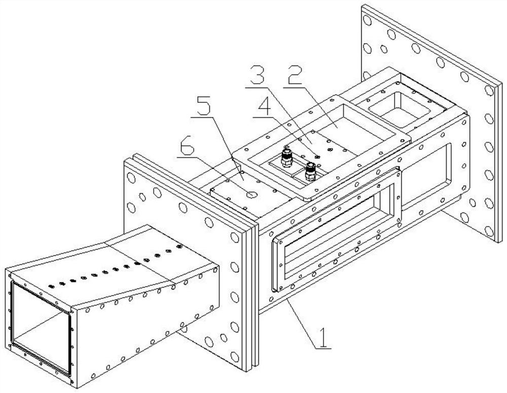
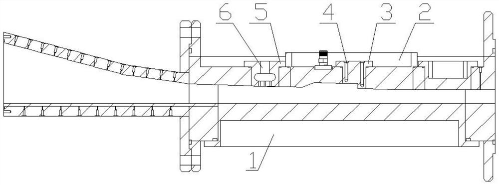
[0021] as attached figure 1 with figure 2 Shown: a kind of fuel blending device of scramjet engine, comprises engine body 1 and the groove 2 that is positioned at the middle part of engine body 1, and the total length of engine body 1 is 1700mm, and the inlet of air is opened on the left side of engine body 1, The inlet is a rectangular opening with a length of 100mm and a width of 50mm. The engine body 1 is bolted with a fuel injection block 3 fitted in the middle of the groove 2, and the fuel injection block 3 is provided with two spaced circular The first injection hole 4, the engine body 1 is also bolted with a jet air injection block 5 fitted on the left side of the groove 2, and the distance between the jet air injection block 5 and the groove 2 is 1 / 2 of the length of the engine. 5%-20%, the jet air injection block 5 is about 845mm away from the inlet of the engine body 1 .

[0022] An "O" type seal ring is installed between the jet air injection block 5 and the oute...


PUM


Abstract

The invention discloses a fuel mixing device of a scramjet engine, and particularly relates to the technical field of scramjet engines. The fuel mixing device of the scramjet engine comprises an engine body and a groove located in the engine body, wherein the engine body is provided with a fuel injection block located in the groove, a plurality of circular first spray holes are formed in the fuelinjection block, a jet air injection block located in one side of the groove is further arranged in the engine body, a plurality of circular second spray holes are formed in the jet air injection block, a metal hose communicating with the second spray holes is formed in the jet air injection block, and gas storage bottles are connected with the metal hose. According to the technical scheme, the fuel mixing device solves the problem that fuel mixing cannot be promoted under the condition that a geometric configuration is not changed, and can be used for improving the mixing efficiency of fuel and air of the scramjet engine.

Description

technical field [0001] The invention relates to the technical field of scramjet engines, in particular to a fuel mixing device for scramjet engines. Background technique [0002] The combustion process of a scramjet is complex, often including fuel injection, atomization, evaporation, mixing, ignition and stable combustion. The flow time of fuel in a scramjet engine is often on the order of milliseconds. Fuel mixing is an important factor to achieve engine starting ignition and stable combustion. If the fuel and air cannot be fully mixed, the scramjet engine cannot achieve a reliable location. Fire, not to mention stable combustion produces positive thrust. Although the best mixing state of fuel is to achieve the proper ratio of chemical reaction between fuel and air, it is often impossible to achieve in practice, or can only be achieved locally. Chemical proper ratio is the most appropriate method and conventional means. [0003] There are many methods of enhanced fuel m...

Claims


Application Information

Patent Timeline
IPC IPC(8): F02K9/44F02K9/58F02K9/60
CPCF02K9/44F02K9/58F02K9/60
Inventor 田野钟富宇杨顺华李季时文肖保国鲁玲李世豪孙光焱张娜
Owner CHINA AERODYNAMICS RES & DEV CENT
Learn More