Air suction purification decontamination valve for air compressor

A technology of decontamination valve and air compressor, applied in mechanical equipment, machine/engine, liquid variable capacity machinery, etc., can solve problems such as troublesome use, and achieve the effect of ensuring normal operation, reducing trouble, and improving adhesion effect.

Inactive Publication Date: 2020-09-15
北京康乾白祥商贸有限公司
View PDF0 Cites 0 Cited by
  • Summary
  • Abstract
  • Description
  • Claims
  • Application Information

AI Technical Summary

Problems solved by technology

[0004] Aiming at the deficiencies of the prior art, the present invention provides an air suction purification and decontamination valve for an air compressor, which has the advantages of purifying the air sucked by the air compressor, and solves the problem that the air compressor needs to suck air from the air when it is working. However, due to impurities in the air, it is necessary to filter the air sucked by the air compressor, but the existing filter device is troublesome to use because it is cleaned and replaced after filtering the air.

Method used


Image

  • Air suction purification decontamination valve for air compressor
  • Air suction purification decontamination valve for air compressor
  • Air suction purification decontamination valve for air compressor

Examples


Embodiment 1

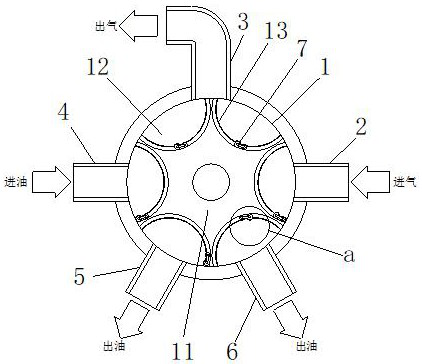
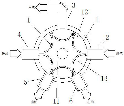
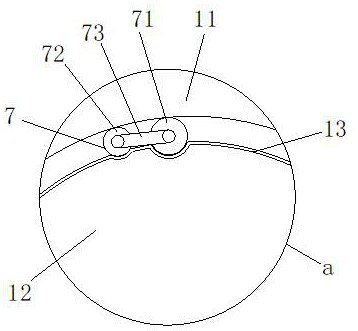
[0029] Embodiment 1, please refer to figure 1 and image 3 , an air suction purifying decontamination valve for an air compressor, comprising a valve body 1, characterized in that: the valve body 1 is a cylindrical barrel, the valve body 1 is fixedly installed with an air inlet pipe 2 and an air outlet pipe 3, and the valve body A rotating body 11 is fixedly installed at the center of 1, the central axis of the rotating body 11 is fixedly connected to the output shaft of the rotating motor, the rotating body 11 rotates counterclockwise in the valve body 1, and the rotating body 11 divides the internal space of the valve body 1 Divided into six processing chambers 12, the air inlet pipe 2 is not connected to the air outlet pipe 3, and the oil inlet pipe 4, the oil outlet pipe 1 and the oil outlet pipe 2 6 are fixedly installed on the valve body 1, and the rotation speed of the motor is opened and controlled to ensure that the rotating body 11 Rotate stably counterclockwise in ...

Embodiment 2

[0030] Embodiment two, please refer to figure 1 and image 3 , on the basis of Embodiment 1, the rotary body 11 is a turntable with six partition plates and the partition plates extend outward. The inner wall of the body 1 forms six identical spaces to ensure that the amount of air sucked by the air compressor from the valve body 1 is constant each time to achieve the effect of quantitative air delivery.

Embodiment 3

[0031] Embodiment three, please refer to figure 1 and image 3 , on the basis of Embodiment 2, the six surfaces of the rotating body 11 are all arc-shaped surfaces, and the oil injected into the processing chamber 12 from the oil outlet pipe 4 can be better distributed in the processing chamber 12 by utilizing the arc-shaped surface characteristics of the rotating body Uniformity improves the adhesion effect of the processing chamber 12 to impurities in the air, and at the same time facilitates the movement of oil in the processing chamber 12, facilitating the transportation and recovery of oil.


PUM


Abstract

The invention relates to the technical field of air compressors, and discloses an air suction purification decontamination valve for an air compressor. The air suction purification decontamination valve for the air compressor comprises a valve body; the valve body is a cylindrical barrel, an air inlet pipe and an air outlet pipe are fixedly mounted on the valve body; a rotating body is fixedly mounted on the center of the valve body, an oil inlet pipe, an oil outlet pipe I and a oil outlet pipe II are further fixedly mounted on the valve body, elastic films are fixedly mounted on the six arc-shaped faces of the rotating body, gaps are formed between the elastic films and the arc-shaped faces of the rotating body, pushing devices are arranged in the gaps, air in a treatment bin is sucked away by the air compressor through the air outlet pipe, and due to the fact that the air inlet pipe does not communicate with the air outlet pipe, only treated air can be sucked from the treatment bin every time air compression is conducted, the air compressor is prevented from directly sucking air from the air, air in the treatment bin is adhered by oil, and then polluted oil is automatically recovered by utilizing the rotating effect of the rotating body, so that the effect of automatically cleaning a filtering device is achieved, and troubles caused by cleaning and replacing of the filteringdevice are reduced.

Description

technical field [0001] The invention relates to the technical field of air compressors, in particular to an air suction purification decontamination valve for air compressors. Background technique [0002] Air compressors have a wide range of applications and are suitable for many fields. Air compressors are often used as a driving source in textile mills. Especially in the cotton spinning industry, clean compressed air is mainly used as a power source. This requires air compressors to be used in textile mills. When working in an air environment with many impurities and lint, it is necessary to ensure that the compressed air and the discharged air are clean, and at the same time prevent these impurities from entering the air compressor and causing damage to the air compressor. The existing The air compressor used in the textile factory generally uses the filtering method to filter the impurities in the air in terms of air purification. Since there are many impurities in the ...

Claims


Application Information

Patent Timeline
Patent Type & Authority Applications(China)
IPC IPC(8): F04B39/10F04B39/16B01D49/00
CPCB01D49/00F04B39/10F04B39/16
Inventor 不公告发明人
Owner 北京康乾白祥商贸有限公司
Why Eureka
Try Eureka