Unlock instant, AI-driven research and patent intelligence for your innovation.

Magnetostrictive TORQUE DETECTION SENSOR

A magnetostrictive, torque detection technology, used in torque measurement, instruments, measuring devices, etc., can solve the problem of reduced detection sensitivity, achieve uniform detection sensitivity, achieve miniaturization, and improve detection sensitivity.

Inactive Publication Date: 2020-09-15
SHINANO KENSHI
View PDF1 Cites 0 Cited by
  • Summary
  • Abstract
  • Description
  • Claims
  • Application Information

AI Technical Summary

Problems solved by technology

[0007] However, in the detection device of the above-mentioned Patent Document 1, although there are few magnetic fluxes in directions different from the desired direction, the magnetic fluxes cancel each other, and the detection sensitivity may be lowered.

Method used


Image

  • Magnetostrictive TORQUE DETECTION SENSOR
  • Magnetostrictive TORQUE DETECTION SENSOR
  • Magnetostrictive TORQUE DETECTION SENSOR

Examples


Embodiment Construction

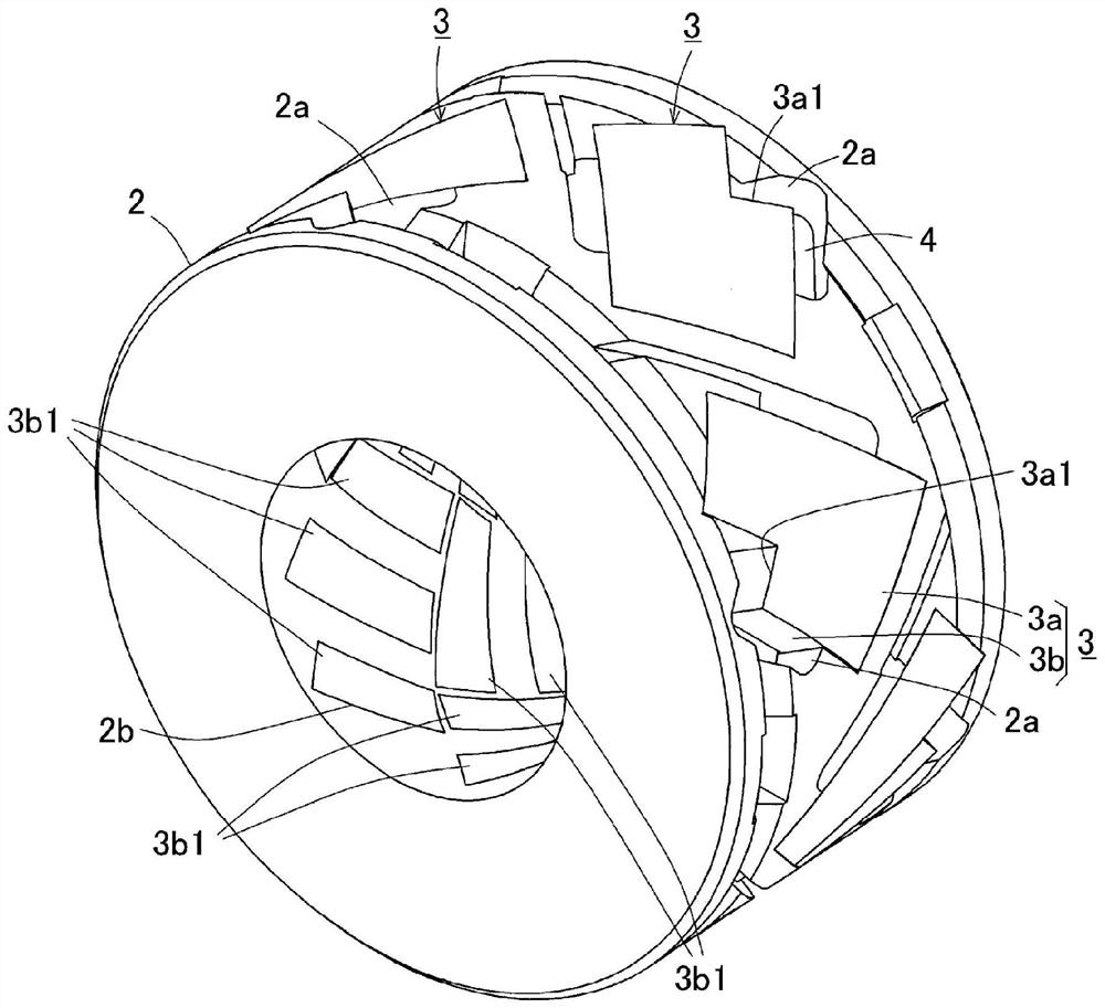
[0036] Hereinafter, an embodiment of the magnetostrictive torque detection sensor of the present invention will be described with reference to the drawings. First, refer to Figure 1 to Figure 7 , the schematic structure of the magnetostrictive torque detection sensor will be described.

[0037] As an example of the object S to be detected, it is desirable to use a material having a large inverse magnetostrictive effect. For example, materials having a large inverse magnetostrictive effect include FeCoV (Permender alloy), Fe-Al (aluminum-iron alloy), Fe-Nix (Permalloy), and spherical graphite cast iron (JIS: FCD70). In addition, the inverse magnetostrictive effect is a phenomenon in which magnetic properties change when stress is applied to the magnet from the outside. In addition, if the subject S is subjected to magnetic annealing in advance as necessary, the torque acting on the subject S can be appropriately detected as will be described in detail later. In addition, ev...


PUM


Abstract

The invention provides a magnetostrictive torque detection sensor which can detect torque generated on the whole circumference of the side surface of a detected object in a uniform state with improveddetection sensitivity and can realize miniaturization of the sensor in the axial direction. A plurality of iron cores (3) having at least three leg parts (3b) connected to each other by a cross-linking part (3a) disposed on the outer peripheral surface side of an insulating cylinder (2) are assembled so as to be arranged at a prescribed angle to the axis (O) of a subject (S) to be detected, and aplurality of leg end surfaces (3b1) face the subject (S) from the inner peripheral surface of the insulating cylinder (2).

Description

technical field [0001] The invention relates to a magnetostrictive torque detection sensor. Background technique [0002] There is a magnetostrictive torque detection device as a method of detecting torque acting on an object to be detected such as a rotating shaft without contact. A pair of coils of the torque detection device are wound around the object to be detected without contact, and a pair of claw pole cores surrounding the inner and outer peripheries of the coils are provided concentrically without contacting the object to be detected. Each iron core has a pair of annular portions provided with pole teeth along the inner peripheral side at both ends of the cylindrical portion, the pole teeth are arranged such that the pole teeth mesh with each other, and assembled so as to face the object to be detected. Each iron core forms a magnetic circuit with the object to be detected, and each iron core is arranged symmetrically with respect to a line segment perpendicular t...

Claims


Application Information

Patent Timeline
IPC IPC(8): G01L3/10
CPCG01L3/103G01L3/102
Inventor 古川顕秀
Owner SHINANO KENSHI
Features
  • R&D
  • Intellectual Property
  • Life Sciences
  • Materials
  • Tech Scout
  • Unparalleled Data Quality
  • Higher Quality Content
  • 60% Fewer Hallucinations
Learn More