Therapeutic instrument for correcting myopia by naked-eye staring

A technology for correcting myopia and therapeutic equipment, applied in the field of therapeutic equipment, can solve problems such as low actual usage rate, inability to alternate between distant and near vision, and limited use conditions

Pending Publication Date: 2020-09-18
李容梅
View PDF0 Cites 0 Cited by
  • Summary
  • Abstract
  • Description
  • Claims
  • Application Information

AI Technical Summary

Problems solved by technology

[0004] The existing home myopia treatment equipment usually needs to be used close to the user's eyes. The virtual perspective area is small, the clarity is extremely poor, the distance cannot be adjusted, and the distance and near vision cannot be alternated. The curative effect is not good. And close to the eyes, it is easy to bring bacteria to the eyes, which brings potential infection risks
The professional medical myopia treatment instrument is bulky, expensive and complicated to operate, so it is not suitable for home use.

Method used


Image

  • Therapeutic instrument for correcting myopia by naked-eye staring
  • Therapeutic instrument for correcting myopia by naked-eye staring
  • Therapeutic instrument for correcting myopia by naked-eye staring

Examples


Embodiment 1

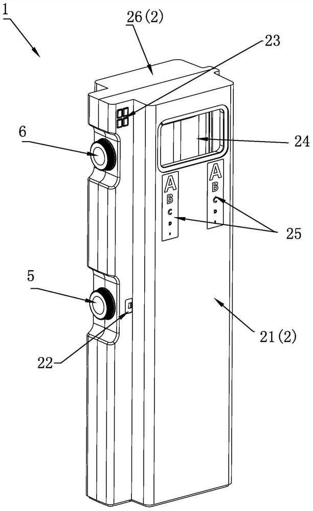
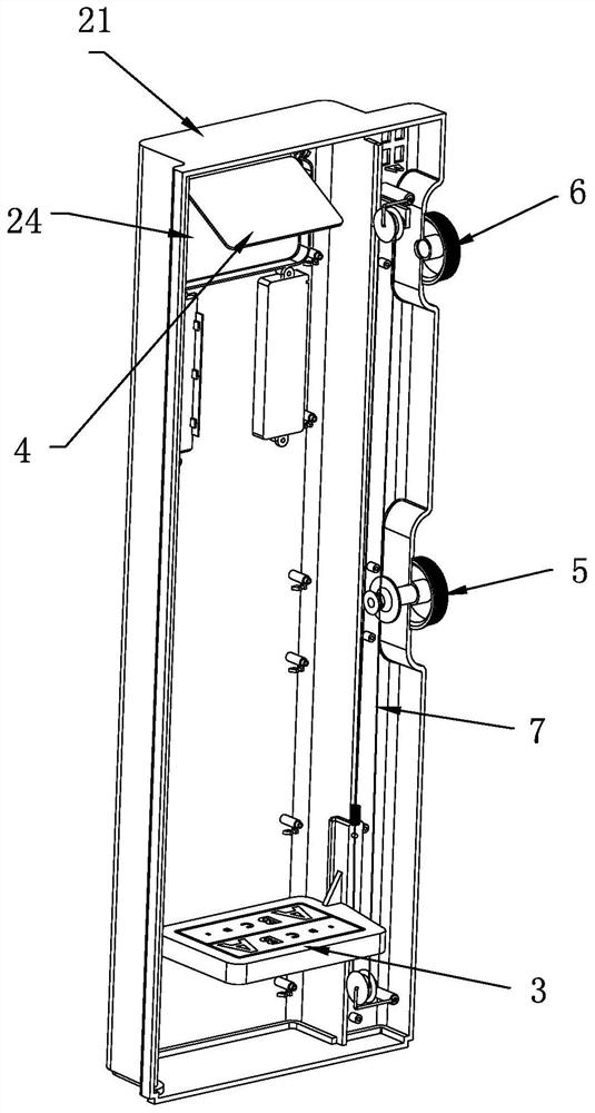
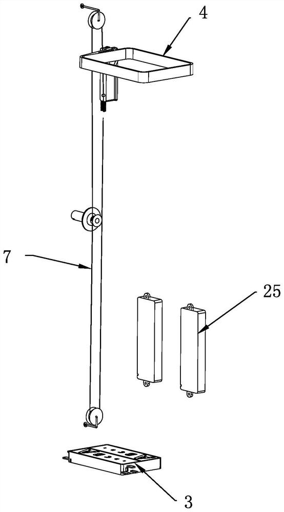
[0069] Such as figure 1 -3, in this embodiment, the object space target plate 3 is arranged at the bottom of the housing 2, and the rear stage reflector 4 is a spherical reflector, which is arranged obliquely above the object space target plate 3, and the object space target plate 3 is connected to the transmission mechanism 7, and the object space target plate 3 can move up and down in the casing 2 by adjusting the image distance adjustment component 5.

[0070] The radius of curvature of the rear-stage reflector 4 is 180-6000mm. Correspondingly, the object focal point position of the rear-stage reflector 4 is calculated according to the paraxial spherical refraction formula, and is approximately on the optical axis from the rear-stage reflector 4 90-3000mm from the center point of the mirror surface.

[0071] The paraxial spherical refraction formula is: (n' / s')-(n / s)=(n'-n) / r;

[0072] n and n' are the refractive indices of the transparent media on both sides of the inter...

Embodiment 2

[0079] Such as Figure 4 As shown in -8, in this embodiment, the object space target plate 3 is arranged on the inner side of the bottom of the housing 2, and the rear stage reflector 4 is a spherical or plane mirror, and it and the object space target plate 3 are arranged on the shell 2 The outside of the bottom inside, that is, the object space target plate 3 and the rear stage reflector 4 are arranged side by side, and the light-through window 24 is located at the bottom of the front cover 21 front.

[0080] In housing 2, be positioned at the top of object space target plate 3 and rear stage reflective mirror 4 and on the optical path between object space target plate 3 and rear stage reflector 4, be provided with by plane or spherical reflector, spherical convex lens A catadioptric system composed of a plurality of optical mirrors in a spherical concave lens designed and combined according to the principle of optical imaging (an optical system composed of a lens and a mirr...


PUM


Abstract

The utility model relates to a therapeutic instrument, which is simple in structure and can gradually improve vision by long-term staring training of eyes in or out of a distance of distinct vision ofeyes, for correcting myopia by naked-eye staring. The therapeutic instrument is placed in a vertical or horizontal posture on a desktop beyond the near point of the eyes of a staring person or hung on a wall beyond the near point of the eyes of the staring person. A light window is arranged on the front of a shell, and a rear-stage reflector capable of clearing imaging character patters on an object space target plate in such a manner that the size of the aperture angle entering the pupils of the staring person is adjustable and located in the near point position of the eyes of the staring person and reflecting out of the shell via the light window is arranged in the position, opposite to the light window, of the shell. The myopic patient can use the therapeutic instrument, under the condition of relaxation of ciliary muscle, the ciliary muscle is trained by adjusting the size of the aperture angle of images in human eyes stage by stage, and the ciliary muscle of myopia can recover to original adjusting capacity after long-term training.

Description

technical field [0001] The invention relates to a therapeutic apparatus capable of correcting myopia, in particular to a therapeutic apparatus capable of achieving a better correction effect after standing at a certain distance and gazing at it with naked eyes after long-term training. Background technique [0002] As we all know, it is very beneficial for the nearsighted people to look far away without naked eyes. For teenagers, long-term training in this way is very likely to make them lose their glasses and restore their vision to normal. [0003] Reasons for myopia: In the natural environment, the pictures that people see are near and far. When the eyes are moving, they need to constantly participate in the focus adjustment to see clearly. In this way, the ciliary muscles of the eyes will follow it frequently. At the same time, under the adjustment of the ciliary muscle, the external scene is clearly imaged on the retina through the pupil and the lens. Nowadays, with th...

Claims


Application Information

Patent Timeline
Patent Type & Authority Applications(China)
IPC IPC(8): A61H5/00
CPCA61H5/00A61H2205/024
Inventor 李容梅
Owner 李容梅
Why Eureka
Try Eureka