Therapeutic instruments for eyesight disease
A disease treatment and vision technology, applied in the field of therapeutic equipment, can solve problems such as not easy to spread to ordinary people's homes, eye irritation, visual fatigue, etc., and achieve the effects of eliminating excessive congestion, improving vision, and improving neurotrophy
- Summary
- Abstract
- Description
- Claims
- Application Information
AI Technical Summary
Problems solved by technology
Method used
Image
Examples
specific Embodiment approach 1
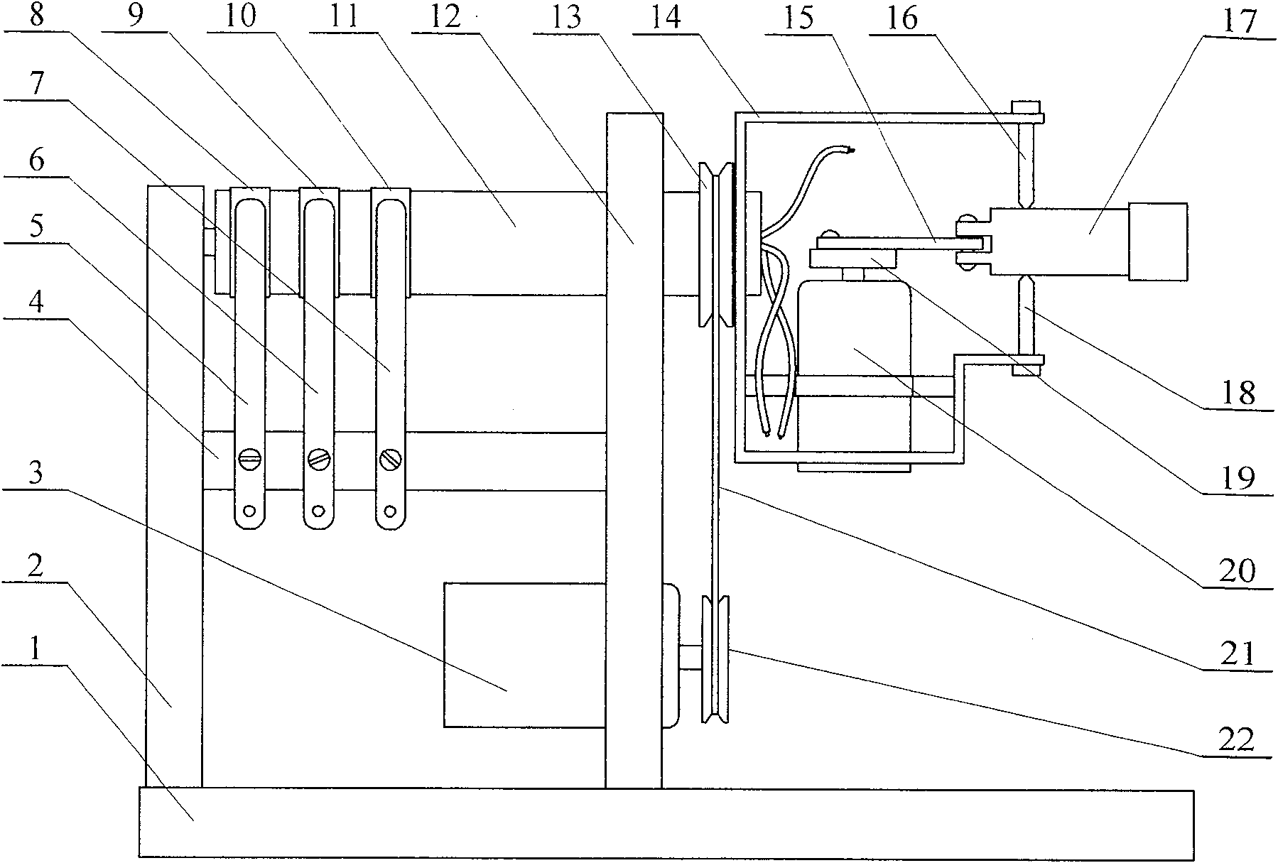
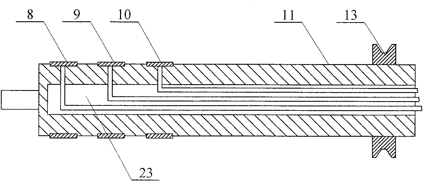
[0007] Specific implementation mode one: as figure 1 , figure 2 As shown, this embodiment consists of a base 1, a first bracket 2, a main motor 3, an insulating rod 4, a first electrode 5, a second electrode 6, a third electrode 7, a first conductive ring 8, a second conductive ring 9, The third conductive ring 10, the rotating shaft 11, the second support 12, the rotating shaft pulley 13, the connecting frame 14, the connecting rod 15, the first screw 16, the laser generator 17, the second screw 18, the crank 19, the auxiliary motor 20, The transmission belt 21 and the main motor pulley 22 are composed, the second bracket 12 is fixed on the middle part of the upper end surface of the base 1, the first bracket 2 is fixed on one side of the upper end surface of the base 1, and the first bracket 2 and the second bracket 12 are arranged parallel to each other. The insulating rod 4 is fixed between the first support 2 and the second support 12, one end of the rotating shaft 11 i...
specific Embodiment approach 2
[0008] Specific implementation mode two: as figure 1 As shown, the main motor 3 of this embodiment is a DC motor. Others are the same as in the first embodiment.
specific Embodiment approach 3
[0009] Specific implementation mode three: as figure 1 As shown, the sub-motor 20 of this embodiment is a DC motor. Others are the same as in the first embodiment.
[0010] Working principle: only the auxiliary motor 20 rotates, and under the action of the crank 19 and the connecting rod 15, the laser generator 17 swings back and forth on both sides around the axis of the first top wire 16 and the second top wire 18, and the laser generator 17 The generated bright spot shines on the curtain wall to form a straight line movement. As long as the main motor 3 rotates a little, the straight line will change the angle, such as horizontal, vertical or the like. Stop the laser generator 17 at a certain angle, only let the main motor 3 rotate, and the bright spots generated by the laser generator 17 irradiate on the curtain wall to form a circular motion. The larger the angle between the laser generator 17 and the rotating shaft 11, the larger the angle The larger the diameter. Whe...
PUM
 Abstract
Description
Claims
Application Information
 - R&D
- Intellectual Property
- Life Sciences
- Materials
- Tech Scout
- Unparalleled Data Quality
- Higher Quality Content
- 60% Fewer Hallucinations
Browse by: Latest US Patents, China's latest patents, Technical Efficacy Thesaurus, Application Domain, Technology Topic, Popular Technical Reports.
© 2025 PatSnap. All rights reserved.Legal|Privacy policy|Modern Slavery Act Transparency Statement|Sitemap|About US| Contact US: help@patsnap.com


