
Therapeutic instruments for eyesight disease

A disease treatment and vision technology, applied in the field of therapeutic equipment, can solve problems such as not easy to spread to ordinary people's homes, eye irritation, complex equipment, etc., to achieve the effect of eliminating excessive congestion, improving vision, and improving adjustment function

Inactive Publication Date: 2008-08-06
崔浩
View PDF3 Cites 3 Cited by
  • Summary
  • Abstract
  • Description
  • Claims
  • Application Information

AI Technical Summary

Problems solved by technology

[0003] The purpose of the present invention is to solve the complex equipment existing in the existing vision disease treatment instrument, which is not easy to spread to ordinary people's homes; the field of vision is too small, which easily causes visual fatigue or directly acts on the cone cells in the macular area of ​​the fundus, which is harmful to people's eyes. There are certain adverse stimulation problems, providing a vision disease treatment instrument

Method used


Image

  • Therapeutic instruments for eyesight disease

Examples


specific Embodiment approach 1

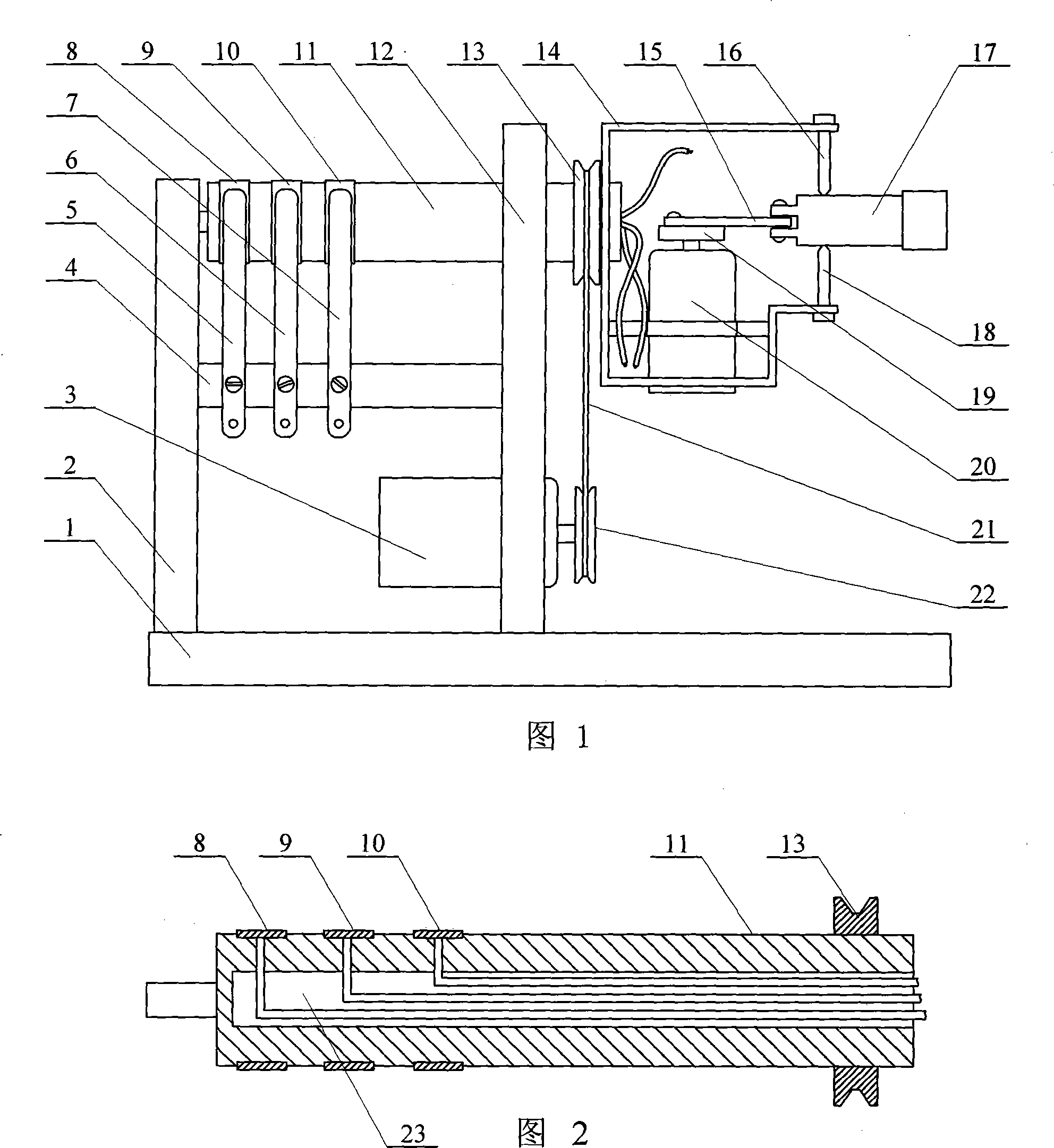
[0007] Embodiment 1: As shown in Figure 1 and Figure 2, this embodiment consists of a base 1, a first bracket 2, a main motor 3, an insulating rod 4, a first electrode 5, a second electrode 6, a third electrode 7, a first A conductive ring 8, a second conductive ring 9, a third conductive ring 10, a rotating shaft 11, a second support 12, a rotating shaft pulley 13, a connecting frame 14, a connecting rod 15, a first top wire 16, a laser generator 17, a second Top wire 18, crank 19, auxiliary motor 20, transmission belt 21 and main motor pulley 22 are composed, the second bracket 12 is fixed on the middle part of the upper end surface of the base 1, the first bracket 2 is fixed on one side of the upper end surface of the base 1, the first The support 2 and the second support 12 are arranged parallel to each other, the insulating rod 4 is fixed between the first support 2 and the second support 12, one end of the rotating shaft 11 is arranged on the first support 2, and the othe...

specific Embodiment approach 2

[0008] Embodiment 2: As shown in FIG. 1 , the main motor 3 of this embodiment is a DC motor. Others are the same as in the first embodiment.

specific Embodiment approach 3

[0009] Embodiment 3: As shown in FIG. 1 , the auxiliary motor 20 in this embodiment is a DC motor. Others are the same as in the first embodiment.

[0010] Working principle: only the auxiliary motor 20 rotates, and under the action of the crank 19 and the connecting rod 15, the laser generator 17 swings back and forth on both sides around the axis of the first top wire 16 and the second top wire 18, and the laser generator 17 The generated bright spot shines on the curtain wall to form a straight line movement. As long as the main motor 3 rotates a little, the straight line will change the angle, such as horizontal, vertical or the like. Stop the laser generator 17 at a certain angle, only let the main motor 3 rotate, and the bright spots generated by the laser generator 17 irradiate on the curtain wall to form a circular motion. The larger the angle between the laser generator 17 and the rotating shaft 11, the larger the angle The larger the diameter. When the axis of the ...


PUM


Abstract

The invention provides a sight disease therapeutic apparatus which relates to a therapeutic apparatus. The invention aims at solving the problems that equipment are relatively complicated, or visual fatigue is easily caused or direct effect on cone cells in a macular area of eyeground has certain pessimal stimulation to eyes existing in the sight disease therapeutic apparatuses. In the invention, a belt pulley of a main motor (22) is connected with the belt pulley of a rotary shaft (13) by a transmission belt (21) in a transmission way; an auxiliary motor (20) is fixed on a connecting yoke (14); a crank (19) is fixed on a motor shaft of the auxiliary electric motor (20); a laser generator (17) is arranged between a first jack bolt (16) and a second jack bolt (18). The sight disease therapeutic apparatus is used for curing a plurality of strabismus diseases, such as paralytic strabismus, heterophoria, intermittent strabismus, consecutive strabismus, microtropia, pseudostrabismus, postoperative strabismus, postoperative residual strabismus, curing functional disorder caused by the holding of extra ocular muscles after orbital fracture, etc., in a rehabilitative way as well as remedying and curing hypermetropia, amblyopia and myopia.

Description

technical field [0001] The invention relates to a therapeutic instrument. Background technique [0002] In vision diseases, such as myopia, paralytic strabismus, cryptic strabismus, intermittent strabismus, secondary strabismus, microstrabismus, angular strabismus, corrective strabismus after surgery, residual strabismus after surgery, extraocular muscle injury after orbital fracture Dysfunction after clamping, hyperopia, amblyopia, etc. will have adverse effects on people's normal life, study and work, and even affect their lives. As a global medical and social problem, strabismus, amblyopia and myopia have received extensive attention all over the world. Devices and instruments for the treatment of vision disorders are also increasingly being marketed. It can be roughly divided into the following three types: ①Application No. 03142288.8, publication date is February 16, 2005, publication No. CN1579319A, titled "Intelligent Children's Amblyopic Strabismus Diagnosis and Tr...

Claims


Application Information

Patent Timeline
IPC IPC(8): A61F9/00A61H5/00A61N5/067
Inventor 崔浩李洪彦
Owner 崔浩
Learn More