Energy-saving and emission-reducing waste gas treatment device

A waste gas treatment device, energy saving and emission reduction technology, applied in mixers with rotary stirring devices, transportation and packaging, chemical/physical processes, etc. The effect of weight, speed of reaction, and effect of use

Inactive Publication Date: 2020-09-18
刘秀秀
View PDF0 Cites 1 Cited by
  • Summary
  • Abstract
  • Description
  • Claims
  • Application Information

AI Technical Summary

Problems solved by technology

[0003] Especially in the field of chemical industry, a large amount of waste gas will inevitably be produced in industrial production and processing. These waste gases contain many harmful substances, such as dust particles, flue gas smoke, odorous gases and toxic and harmful gases. In order to prevent the discharged waste gas from polluting the external environment, the function of the existing industrial waste gas treatment device is relatively simple in the process of processing, and the treatment effect of the waste gas is not very obvious, so that the discharged gas is easy to pollute the environment, thus affecting the People's health, therefore, in view of the above status quo, there is an urgent need to develop an energy-saving and emission-reducing waste gas treatment device to overcome the deficiencies in current practical applications

Method used


Image

  • Energy-saving and emission-reducing waste gas treatment device
  • Energy-saving and emission-reducing waste gas treatment device
  • Energy-saving and emission-reducing waste gas treatment device

Examples


Embodiment Construction

[0022] The technical solution of this patent will be further described in detail below in conjunction with specific embodiments.

[0023] Embodiments of the present patent are described in detail below, examples of which are shown in the drawings, wherein the same or similar reference numerals designate the same or similar elements or elements having the same or similar functions throughout. The embodiments described below by referring to the figures are exemplary and are only used for explaining the patent, and should not be construed as limiting the patent.

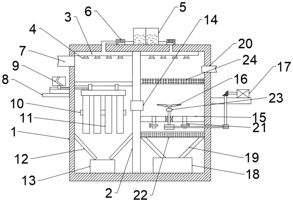
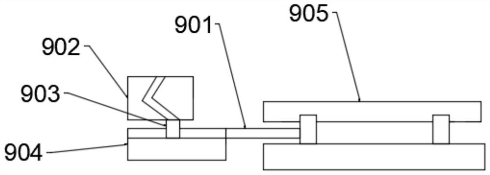
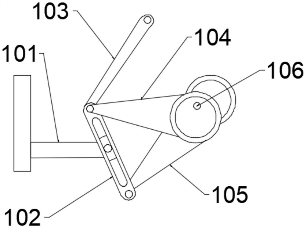
[0024] see Figure 1-4 , in an embodiment of the present invention, an energy-saving and emission-reducing exhaust gas treatment device includes a casing 1, an air inlet 7 is provided at the left end of the casing 1, and a mounting frame 8 is fixedly connected to the outer surface of the casing 1, and the mounting frame 8. A drive mechanism 9 is provided on the upper surface, and the drive mechanism 9 includes a connec...


PUM


Abstract

The invention relates to the technical field of energy conservation and emission reduction, and in particular, relates to an energy-saving and emission-reducing waste gas treatment device including ashell; an air inlet is formed in the left end of the shell; the outer surface of the shell is fixedly connected with a mounting frame; a driving mechanism is arranged on the upper surface of the mounting frame; the driving mechanism comprises a connecting rod; a bracket is fixedly connected to the position, close to the bottom, of the connecting rod; a vibration device is arranged at the other endof the bracket; a filter cloth bag is arranged at one end of the vibration device; a guide rod is arranged below the filter cloth bag; a dust collection box is arranged at the lower end of the guiderod; a baffle is fixedly connected between the upper and lower inner walls of the shell; a communicating pipe is fixedly connected to the position, close to the filtering cloth bag, of the baffle; theright end of the communicating pipe is provided with a connecting plate, the upper end of the connecting plate is provided with a rotating blade, and the lower end of the rotating blade is connectedwith a transmission assembly. According to the waste gas treatment device, by arranging the driving mechanism, the vibration device and the transmission assembly, the waste gas treatment effect of thewaste gas treatment device is good, and pollution of exhausted gas to the environment is effectively avoided.

Description

technical field [0001] The invention relates to the technical field of energy saving and emission reduction, in particular to a waste gas treatment device for energy saving and emission reduction. Background technique [0002] With the development of social economy, energy saving and emission reduction are becoming more and more important in people's life. Energy saving and emission reduction refers to saving material resources and energy resources, reducing waste and environmentally harmful emissions, also known as saving energy and reducing environmentally harmful emissions. [0003] Especially in the field of chemical industry, a large amount of waste gas will inevitably be produced in industrial production and processing. These waste gases contain many harmful substances, such as dust particles, flue gas smoke, odorous gases and toxic and harmful gases. In order to prevent the discharged waste gas from polluting the external environment, the function of the existing ind...

Claims


Application Information

Patent Timeline
IPC IPC(8): B01D46/00B01D46/02B01D53/14B01F7/16B01F15/00
CPCB01D46/0054B01D46/023B01D53/14B01D46/60B01D46/66B01D46/76B01F27/808B01F35/31B01F2101/25
Inventor 刘秀秀
Owner 刘秀秀
Why Eureka
Try Eureka