
An assembled connection node

A connection node and assembly technology, applied in the direction of architecture, building structure, etc., can solve the problems of insufficient connection stiffness, too many components at the node, and unstable quality, so as to enhance the integrity and increase the horizontal shear resistance Force, the effect of reducing the number of components

Active Publication Date: 2021-12-17
HUAIYIN INSTITUTE OF TECHNOLOGY
View PDF11 Cites 0 Cited by
  • Summary
  • Abstract
  • Description
  • Claims
  • Application Information

AI Technical Summary

Problems solved by technology

Most of the existing prefabricated joints are mainly connected by wet method, that is, the prefabricated beams and prefabricated columns are integrally connected by post-cast concrete to form rigid joints, but there are disadvantages such as unstable quality and large workload of on-site pouring
However, the dry connection method has problems such as too many components at the nodes, and the connection stiffness cannot meet the requirements.

Method used


Image

  • An assembled connection node
  • An assembled connection node
  • An assembled connection node

Examples


Embodiment 1

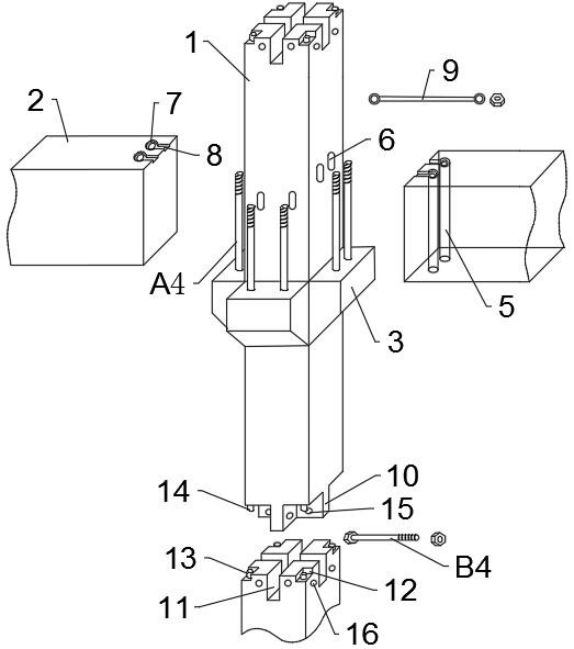
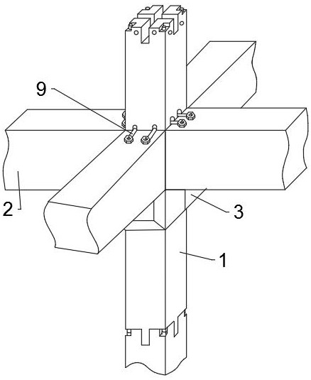
[0034] A new type of prefabricated connection node, comprising a prefabricated corbel column 1 and a prefabricated beam 2, at least one set of corbels 3 of the prefabricated corbel column 1 is provided, and two of the corbels 3 in one set are symmetrical to the prefabricated The corbel 1 and the corbel 3 are usually arranged at the waist of the prefabricated corbel 1,

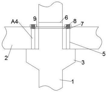
[0035] Screw A4, the screw A4 is fixed on the corbel and parallel to the prefabricated corbel column 1, and the end of the prefabricated beam 2 rests on the corbel 3 and is connected by bolt fit;

[0036] The first through hole 5, the first through hole 5 runs through the end of the prefabricated beam 2 and corresponds to the screw A4; the screw A4 passes through the first through hole 5 and extends to the first through hole 5 Out of a through hole 5;

[0037] Groove, the groove is set on the end surface of the prefabricated beam 2, including the first groove 7 set on the upper end of the first through hole 5 ...

Embodiment 2

[0041] According to the prefabricated height or construction requirements, different corbels can be connected to achieve the required length. On the basis of the above-mentioned embodiment 1, this embodiment 2 only makes improvements in the connection mode of the prefabricated corbel column 1, and the node connection mode between the prefabricated corbel column 1 and the prefabricated beam 2 is the same as above, I won't go into details.

[0042] There may be multiple prefabricated corbels 1, and the prefabricated corbels 1 are connected by a mortise and tenon structure.

[0043]The mortise and tenon structure includes a mortise 10 at one end of the prefabricated corbel 1 and a mortise 11 at the other end of the prefabricated corbel 1. The mortise 10 is cross-shaped, and the mortise 11 is in line with the The tenon 10 matches the cross groove, and the tenon 10 and the mortise 11 are fixed by means of bolt connection.

[0044] A square notch 12 is reserved at the four corners...


PUM


Abstract

The invention discloses a novel assembled connection node. It includes prefabricated corbel columns and prefabricated beams, and also includes screw rods fixed on the corbels and parallel to the prefabricated corbel columns, and the ends of the prefabricated beams rest on the corbels and are fitted by bolts Connection; through the first through hole corresponding to the screw rod at the end of the prefabricated beam; the groove is opened on the surface of the end of the prefabricated beam, including the upper end of the first through hole with a diameter larger than The first groove of the first through hole also includes a second groove perpendicular to the width direction of the prefabricated beam, one end of the second groove communicates with the first groove, and the other end extends to the The edge of the end; the two ends of the tie rod shaft are set as rings, the size of the shaft matches the second groove, the outer diameter of the ring matches the size of the first groove, and the inner diameter The diameter of the first through hole is the same as that of the first through hole; the second through hole is opened parallel to the width direction of the prefabricated corbel column.

Description

technical field [0001] The invention belongs to the field of construction, and in particular relates to a novel assembled connection node. Background technique [0002] Prefabricated concrete building is the most important way of building industrialization. It has many advantages such as improving quality, shortening construction period, saving energy, reducing consumption, and clean production. At present, with the rapid development of my country's economy, the construction industry, like other industries, is undergoing industrial technological transformation, and prefabricated concrete buildings have begun to glow with new vitality. Compared with cast-in-place concrete structures, prefabricated concrete frame structures have It has the advantages of high efficiency and environmental protection, energy saving, less wet work on site, and easy management. Many high-quality buildings have been built with prefabricated structures, and the building system has also used foreign e...

Claims


Application Information

Patent Timeline
Patent Type & Authority Patents(China)
IPC IPC(8): E04B1/21
CPCE04B1/21
Inventor 高延安董云刘泽俊
Owner HUAIYIN INSTITUTE OF TECHNOLOGY
Learn More