Automotive lock structure, automotive door lock and automobile

A technology of car locks and deadbolts, applied in the field of locks, can solve the problems of complex transmission mechanism of locks, unfavorable manufacturing cost of locks, large overall volume of locks, etc., and achieve the effect of simplified transmission mechanism, fewer internal transmission mechanisms, and good locking effect.

Inactive Publication Date: 2020-09-18
QINGDAO TIANCHENJIACHUANG AUTO PARTS CO LTD
View PDF0 Cites 1 Cited by
  • Summary
  • Abstract
  • Description
  • Claims
  • Application Information

AI Technical Summary

Problems solved by technology

[0002] The locking process of the car door lock mainly includes two processes. The first process is to press the door into a fully locked state, and the second process is to lock the car lock so that the door cannot be opened. The principle of the tight state is to use the lock tongue and the brake parts to cooperate, and cooperate with the external matching lock cylinder to press the door tightly. The locking of the car lock is to cut off the connection between the unlocking part and the brake part

Method used


Image

  • Automotive lock structure, automotive door lock and automobile
  • Automotive lock structure, automotive door lock and automobile
  • Automotive lock structure, automotive door lock and automobile

Examples


Embodiment 1

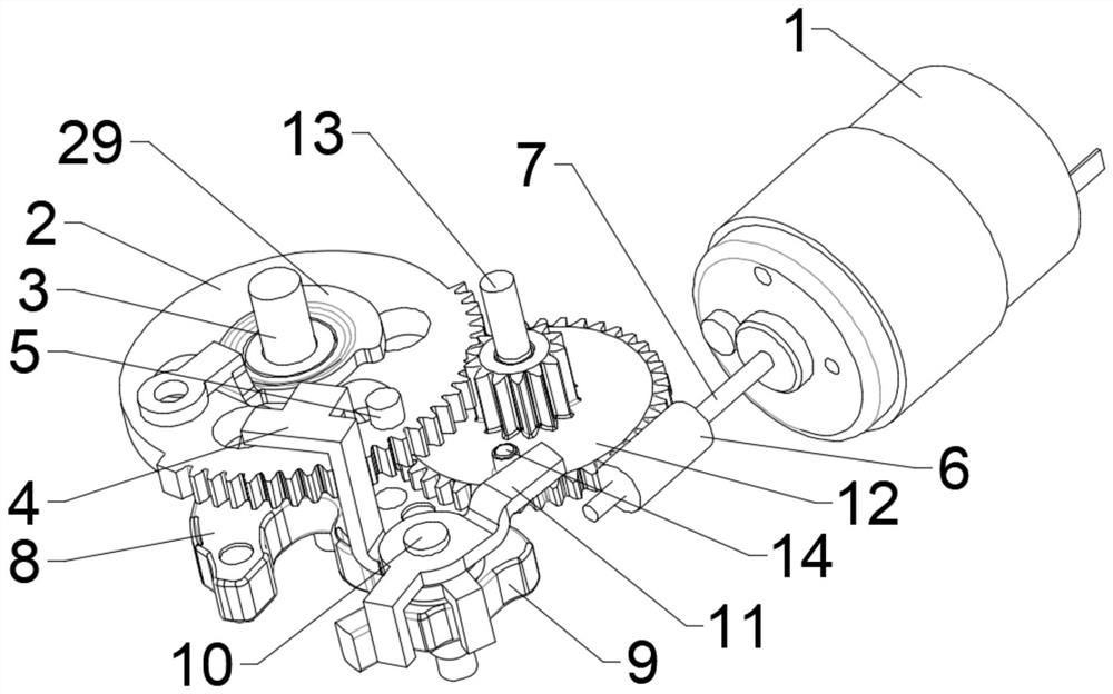
[0049] Such as Figure 1-5 As shown, the present embodiment provides a car lock structure, including: a driving member 1, a rotating member 2, a lock tongue 8 for clamping a lock cylinder, a braking member 9 for locking the lock tongue 8, and a driving member 9 for driving The brake part 9 is unlocked with the unlocking part 29 of the lock tongue 8 and the linkage part 4 is used to contact and cooperate with the unlocking part 29 to realize unlocking.

[0050] The driving part 1 is connected with the rotating part 2 in transmission, and the rotating part 2 is driven to rotate by the driving part 1. The driving part 1 drives the dead bolt 8 to rotate through the rotating part 2 and cooperates with the braking part 9 to realize the locking of the locking cylinder.

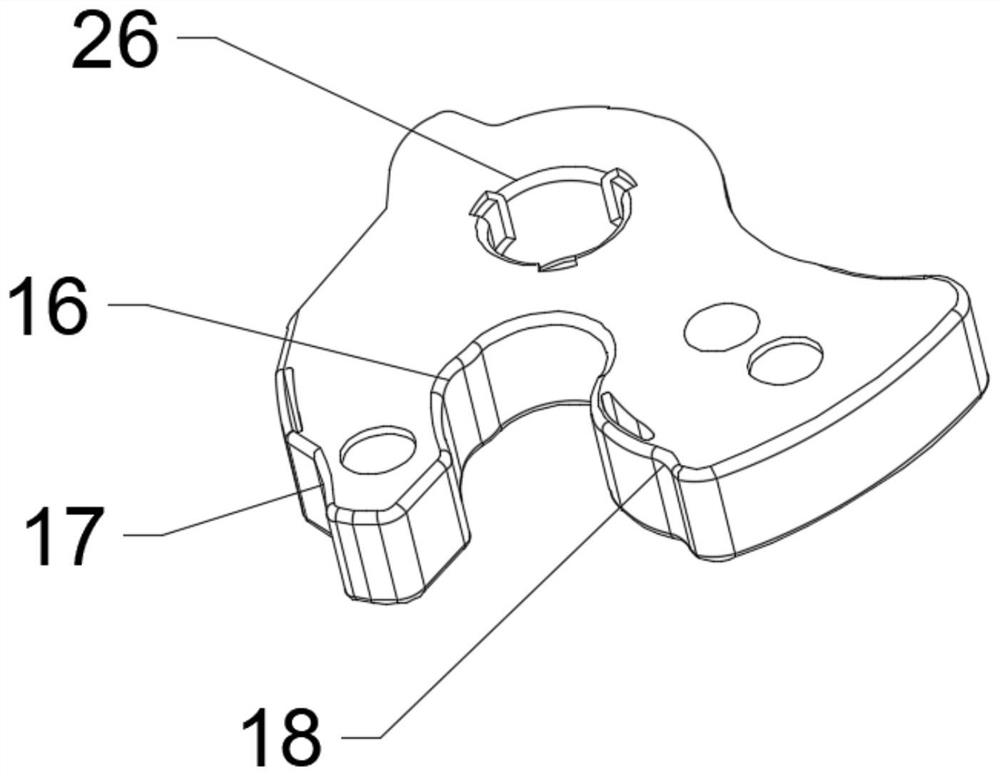
[0051] The lock tongue 8 is in transmission connection with the rotating member 2, and the lock tongue 8 rotates with the rotating member 2. The lock tongue 8 is provided with a lock groove 16 for holding the lock cy...

Embodiment 2

[0082] This embodiment provides a car lock structure, including a driving part 1, a rotating part 2, a lock bolt 8 for holding a lock cylinder, a brake part 9 for locking the lock bolt 8, and a brake part 9 for driving the lock cylinder. The unlocking part 29 that is unlocked with the lock tongue 8 and the linkage 4 that is used to contact and cooperate with the unlocking part 29 to realize unlocking.

[0083] The driving member 1 is in transmission connection with the rotating member 2, and the rotating member 2 is driven to rotate through the driving member 1 . The lock tongue 8 is connected with the rotating member 2 and moves accordingly, so that the lock tongue 8 is beneficial to hold the lock cylinder.

[0084] Linkage piece 4 is connected on the brake piece 9, and one end of linkage piece 4 extends to the stroke position of rotating piece 2, and is positioned on the stroke track of unlocking part 29, when pulling unlocking part 29 to move, contacts with linkage piece 4,...

Embodiment 3

[0089] This embodiment provides a car lock structure, including a driving part 1, a rotating part 2, a lock bolt 8 for holding a lock cylinder, a brake part 9 for locking the lock bolt 8, and a brake part 9 for driving the lock cylinder. The unlocking part 29 that is unlocked with the lock tongue 8 and the linkage 4 that is used to contact and cooperate with the unlocking part 29 to realize unlocking.

[0090] The driving member 1 is in transmission connection with the rotating member 2, and the rotating member 2 is driven to rotate through the driving member 1 . The lock tongue 8 is connected with the rotating member 2 and moves accordingly, so that the lock tongue 8 is beneficial to hold the lock cylinder.

[0091] Linkage piece 4 is connected on the brake piece 9, and one end of linkage piece 4 extends to the stroke position of rotating piece 2, and is positioned on the stroke track of unlocking part 29, when pulling unlocking part 29 to move, contacts with linkage piece 4,...


PUM


Abstract

The invention relates to an automotive lock structure, an automotive door lock and an automobile, and belongs to the technical field of locks. The automotive lock structure comprises a driving part, arotating part, a lock bolt, a braking part, an unlocking part and a linkage part. The driving part and the rotating part are connected in a transmission mode. The lock bolt is used for clamping a lock column and connected with the rotating part in a transmission mode. The braking part is used for cooperating with the lock bolt to conduct locking operation, and the lock bolt is driven by the driving part to rotate to cooperate with the braking part so as to achieve suction combination locking operation. The unlocking part is used for driving the braking part and the lock bolt to achieve unlocking operation. The linkage part is used for making contact with the unlocking part and cooperating with the unlocking part to achieve unlocking operation. The linkage part is connected to the brakingpart. One end of the linkage part extends to the stroke position of the rotating part and located on the stroke track of the unlocking part, the linkage part is poked to keep away from the unlocking part through the rotation of the rotating part in the stroke, and locking operation is achieved. The automotive lock structure adopts a power source to achieve suction combination and locking operation, the transmission mechanism is simplified, and the manufacturing cost is reduced.

Description

technical field [0001] The invention belongs to the technical field of locks, and in particular relates to a car lock structure, a car door lock and a car. Background technique [0002] The locking process of the car door lock mainly includes two processes. The first process is to press the door into a fully locked state. The second process is to lock the car lock so that the door cannot be opened. The principle of the tight state is to use the lock tongue and the brake parts to cooperate, and cooperate with the external matching lock cylinder to press the door tightly. The locking of the car lock is to cut off the connection between the unlocking part and the brake parts, so that the door cannot be opened. [0003] The current car door locks usually use two power sources, one of which is used to drive the lock tongue to rotate to achieve the locked state, and the second power source is used to connect the kinetic energy transfer relationship between the unlocking part and t...

Claims


Application Information

Patent Timeline
IPC IPC(8): E05B81/06E05B81/34E05B85/26
CPCE05B81/06E05B81/34E05B85/26
Inventor 鄂俊邑汪海周永俭
Owner QINGDAO TIANCHENJIACHUANG AUTO PARTS CO LTD
Why Eureka
Try Eureka