
Electromagnetic energy collector based on metasurface

An electromagnetic energy and collector technology, applied in the field of collectors, can solve problems such as the inability to meet the miniaturization requirements of wireless energy harvesting devices, the complex structure of the metasurface, and the large size of rectennas, and achieve reduced polarization sensitivity and energy harvesting Efficiency simplification and efficiency improvement

Active Publication Date: 2020-09-18
UNIV OF ELECTRONICS SCI & TECH OF CHINA
View PDF12 Cites 5 Cited by
  • Summary
  • Abstract
  • Description
  • Claims
  • Application Information

AI Technical Summary

Benefits of technology

This patented technology uses an electric field device called a meta surface made up from tiny wires or rods arranged at regular intervals along its length for absorbing solar rays without affecting their own power supply. It also includes features like smaller sizes, lower profiles, less secondary emissions, reduced noise levels, improved energy capture efficacy, simplified circuits, increased efficiency over previous designs, etc., making them suitable for use in various applications such as radio frequency identification (RFID) tags used for tracking purposes.

Problems solved by technology

This patented problem addressed in this Patents relating to space wireless communication involves reducing its sizes while maintaining efficient energy extraction from electric fields without consuming too much material or requiring complicated structures.

Method used


Image

  • Electromagnetic energy collector based on metasurface
  • Electromagnetic energy collector based on metasurface
  • Electromagnetic energy collector based on metasurface

Examples


Embodiment Construction

[0031] The specific embodiments of the present invention are described below so that those skilled in the art can understand the present invention, but it should be clear that the present invention is not limited to the scope of the specific embodiments. For those of ordinary skill in the art, as long as various changes Within the spirit and scope of the present invention defined and determined by the appended claims, these changes are obvious, and all inventions and creations using the concept of the present invention are included in the protection list.

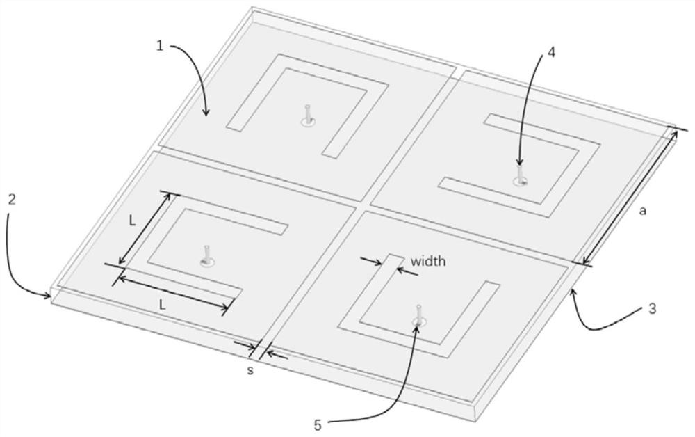
[0032] According to an embodiment of the present application, refer to figure 1 , the metasurface-based electromagnetic energy harvester of this solution includes an upper metal layer 1 , a lower metal layer 3 , metal vias 4 , and a dielectric layer 2 between the upper metal layer 1 and the lower metal layer 3 .

[0033] Each of the above components will be described in detail below

[0034] The upper metal layer 1 is prin...


PUM

PropertyMeasurementUnit
Heightaaaaaaaaaa
Lengthaaaaaaaaaa
Widthaaaaaaaaaa

Abstract

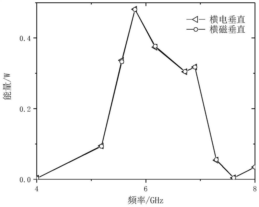
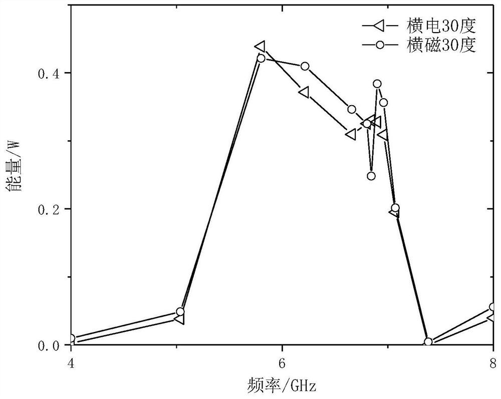
The invention discloses an electromagnetic energy collector based on a metasurface. The electromagnetic energy collector comprises an upper metal layer, a lower metal layer, metal through holes and adielectric layer located between the upper metal layer and the lower metal layer. The upper metal layer comprises four identical U-shaped groove square patches, and the four identical U-shaped groovesquare patches are rotationally symmetrical; a circular hole is formed in the lower metal layer, and the position of the circular hole coincides with the central position of the U-shaped groove squarepatches; each metal through hole is formed in the geometric center of one U-shaped groove square patch, penetrates through the dielectric layer and is perpendicular to the lower metal layer; and a resistor is connected between the bottom end of the metal through hole and the lower metal layer. The electromagnetic energy collector has very good energy absorption capability, unclear polarization and angle stability at 5.8 GHz, and can be used for microwave energy transmission and collection of environmental electromagnetic waves in a complex electronic environment.

Description


Claims


Application Information

Patent Timeline
Owner UNIV OF ELECTRONICS SCI & TECH OF CHINA
Learn More