A sports leisure device
A sports device and sports technology, applied to sports accessories, gymnastics equipment, tennis, etc., can solve the problems of single, unsuitable outdoor leisure, etc.
- Summary
- Abstract
- Description
- Claims
- Application Information
AI Technical Summary
Problems solved by technology
Method used
Image
Examples
Embodiment 1
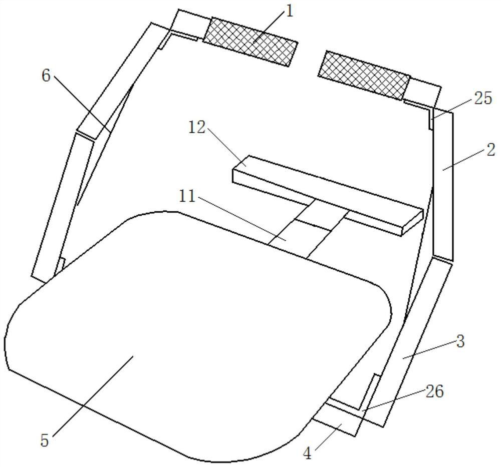
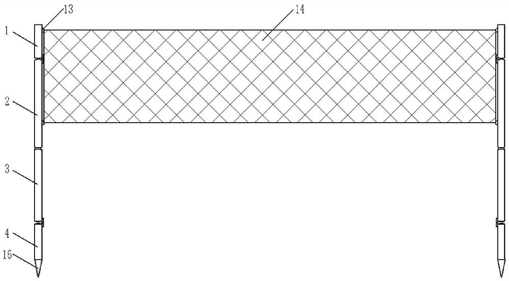
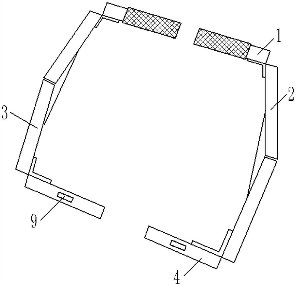
[0027]SeeFigure 1 to 6The embodiment of the present invention provides a sports leisure motion device including a support mechanism and a support mechanism including a first rod body 1, and the first end of the first rod 1 is hinged by the first support hinge 25 through the first support hinge 25. The lower end of the second rod body 3 is connected to the upper end of the third rod body 3, and the lower end of the third rod body 3 is hinged to the upper end of the fourth rod body 4; the angle adjustment assembly includes symmetrical 2 2 2 The two support rods 6, the upper ends of the two support rods 6 are hinged in the middle of the second rod body 2, and the lower end of the two support rods 6 is fixedly connected by the slider 7, and the slider 7 and the longitudinal direction of the third rod 3 The first slide 8 is slidable, and a locking mechanism for locking the slider 7 is provided on the third rod body 3, and the locking mechanism includes a lock block 17, and a lock block i...
Embodiment 2
[0033]The difference from the first embodiment is only that the second rod body 2 includes an outer sleeve 19 and an inner sleeve rod 20, and the outer sleeve 19 is provided with a positioning bolt 21, and both ends and lower ends of the inner sleeve 20 are provided. When the screw hole is positioned, the positioning bolt 21 is fitted to the positioning screw hole provided in the lower end of the inner sleeve 20, and when in the contracted state, the positioning bolt 21 is fitted with the positioning screw hole provided in the upper end of the inner sleeve 20. The upper end of the internal sleeve 20 is hinged from the first rod body 1, the lower end of the outer sleeve 19 through the upper end of the third rod 3 by an angle adjustment component; the second rod body 2 in the present embodiment is from the outer sleeve 19 and the interior The sleeve 20 is composed of, and the inner sleeve 20 can be extended along the outer sleeve 19, when used as the temporary ball support rod, when t...
Embodiment 3
[0035]The difference from the first embodiment is only the second chute 22 in the fourth rod body 4, and the second chute 22 is slidably connected to the slider 23, and the slider 23 is passed through the spring 24 and the cone 16. The first groove connection opened on the side wall; the bottom of the fourth rod body 4 is provided with a second groove fixed to the slider 23, the upper end of the second recess is a curved structure; when needed to be supported After the institution is inserted into the ground, the cone 16 is pulled by hand, and the cone 16 drives the slider 23 to slide down the second chute 22, when the cone 16 moves to the bottom of the fourth rod 4, in the spring 24 Under the action, the slider 23 is ejected to the second groove, so that the cone 16 is fixed, and the entire support mechanism can be fixed inserted into the ground.
PUM
 Abstract
Description
Claims
Application Information
 - R&D
- Intellectual Property
- Life Sciences
- Materials
- Tech Scout
- Unparalleled Data Quality
- Higher Quality Content
- 60% Fewer Hallucinations
Browse by: Latest US Patents, China's latest patents, Technical Efficacy Thesaurus, Application Domain, Technology Topic, Popular Technical Reports.
© 2025 PatSnap. All rights reserved.Legal|Privacy policy|Modern Slavery Act Transparency Statement|Sitemap|About US| Contact US: help@patsnap.com


