
Dust suction method for strip steel uncoiler

A technology of uncoiler and steel strip, which is applied in the direction of cleaning methods and appliances, chemical instruments and methods, and dust removal, etc. It can solve the problems of dust concentration, poor dust removal effect, and difficult dust treatment, and achieves stable structure, small space occupation, and The effect of simple structure

Active Publication Date: 2022-02-25
CISDI SHANGHAI ENG CO LTD
View PDF9 Cites 0 Cited by
  • Summary
  • Abstract
  • Description
  • Claims
  • Application Information

AI Technical Summary

Problems solved by technology

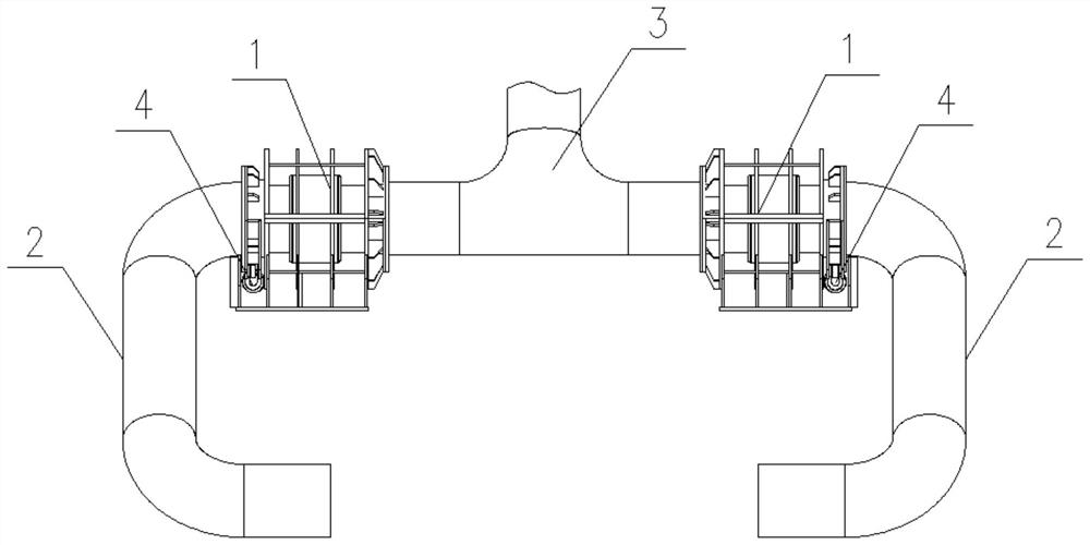
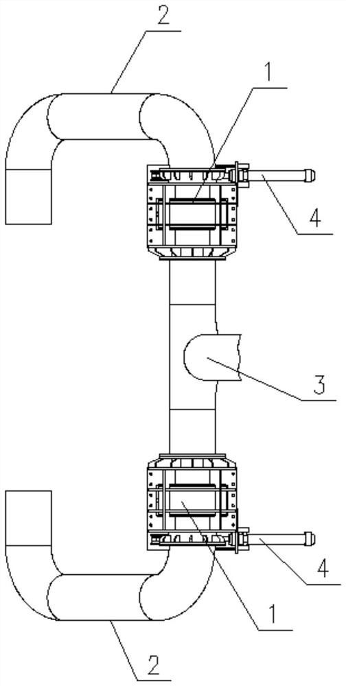
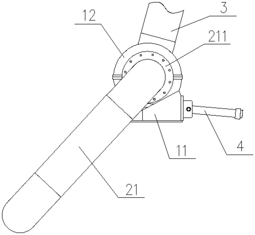
[0003] In view of the above-mentioned shortcomings of the prior art, the object of the present invention is to provide a strip decoiler dust suction method, a dust suction device and a strip decoiler, which are used to solve the dust concentration in the decoiler area of ​​the strip decoiler in the prior art. , Difficult dust handling, poor dust removal effect, etc.

Method used


Image

  • Dust suction method for strip steel uncoiler
  • Dust suction method for strip steel uncoiler
  • Dust suction method for strip steel uncoiler

Examples


Embodiment Construction

[0048] Embodiments of the present invention are described below through specific examples, and those skilled in the art can easily understand other advantages and effects of the present invention from the content disclosed in this specification. The present invention can also be implemented or applied through other different specific implementation modes, and various modifications or changes can be made to the details in this specification based on different viewpoints and applications without departing from the spirit of the present invention.

[0049] It should be noted that the diagrams provided in this embodiment are only schematically illustrating the basic idea of ​​the present invention, and only the components related to the present invention are shown in the diagrams rather than the number, shape and shape of the components in actual implementation. Dimensional drawing, the type, quantity and proportion of each component can be changed arbitrarily during actual impleme...


PUM


Abstract

The invention relates to the technical field of strip steel production, in particular to a strip steel uncoiler dust suction method, a dust suction device and a strip steel uncoiler. The strip steel uncoiler dust suction method is to set a dust suction device in the uncoiling area, and the dust suction device sucks dust during the process of circulating and swinging along the uncoiling area. The beneficial effect of the present invention is: by adopting the method of swinging dust suction, the residence time in the dust producing area can be selected according to the demand, which not only increases the effective dust collection area, but also reduces the space occupied by the equipment, and improves the dust removal effect.

Description

technical field [0001] The invention relates to the technical field of strip steel production, in particular to a strip steel uncoiler dust suction method, a dust suction device and a strip steel uncoiler. Background technique [0002] The incoming material of the uncoiler unit on the strip leveling production line is the cooled steel coil. Since the steel coil must pass through the laminar flow cooling device to cool the high-temperature strip to the coiling temperature after rolling, this process will bring water into the steel coil. Inside the coil, after the steel coil is cooled, an oxide layer will be formed on the surface of the strip. After entering the smoothing process, the strip is reversely bent when uncoiling, especially at the strip stripping point and the reverse bend at the entrance of the pinch roller. A large amount of dust from the peeling off of the oxide layer permeated the area, polluting the environment and affecting the health of personnel in the work ...

Claims


Application Information

Patent Timeline
Patent Type & Authority Patents(China)
IPC IPC(8): B08B15/00B21C47/18
CPCB08B15/002B21C47/18
Inventor 邹中升
Owner CISDI SHANGHAI ENG CO LTD
Learn More