Forming die for mechanical manufacturing and forming machining method of forming die

A technology for forming molds and machinery manufacturing, applied in the direction of pushing out equipment, etc., can solve the problems that cannot be formed quickly, and that the workpiece cannot be separated from the mold.

Pending Publication Date: 2020-09-22
WUHAN UNIV OF TECH
View PDF0 Cites 0 Cited by
  • Summary
  • Abstract
  • Description
  • Claims
  • Application Information

AI Technical Summary

Problems solved by technology

The existing forming die cannot quickly form a space for stamping and forming when it is in use, and it often cannot quickly and smoothly separate the forming workpiece from the die when it is demolded. Therefore, we propose a forming die for mechanical manufacturing and its Forming processing method to solve the problems mentioned in the background art above

Method used


Image

  • Forming die for mechanical manufacturing and forming machining method of forming die
  • Forming die for mechanical manufacturing and forming machining method of forming die
  • Forming die for mechanical manufacturing and forming machining method of forming die

Examples


Embodiment 1

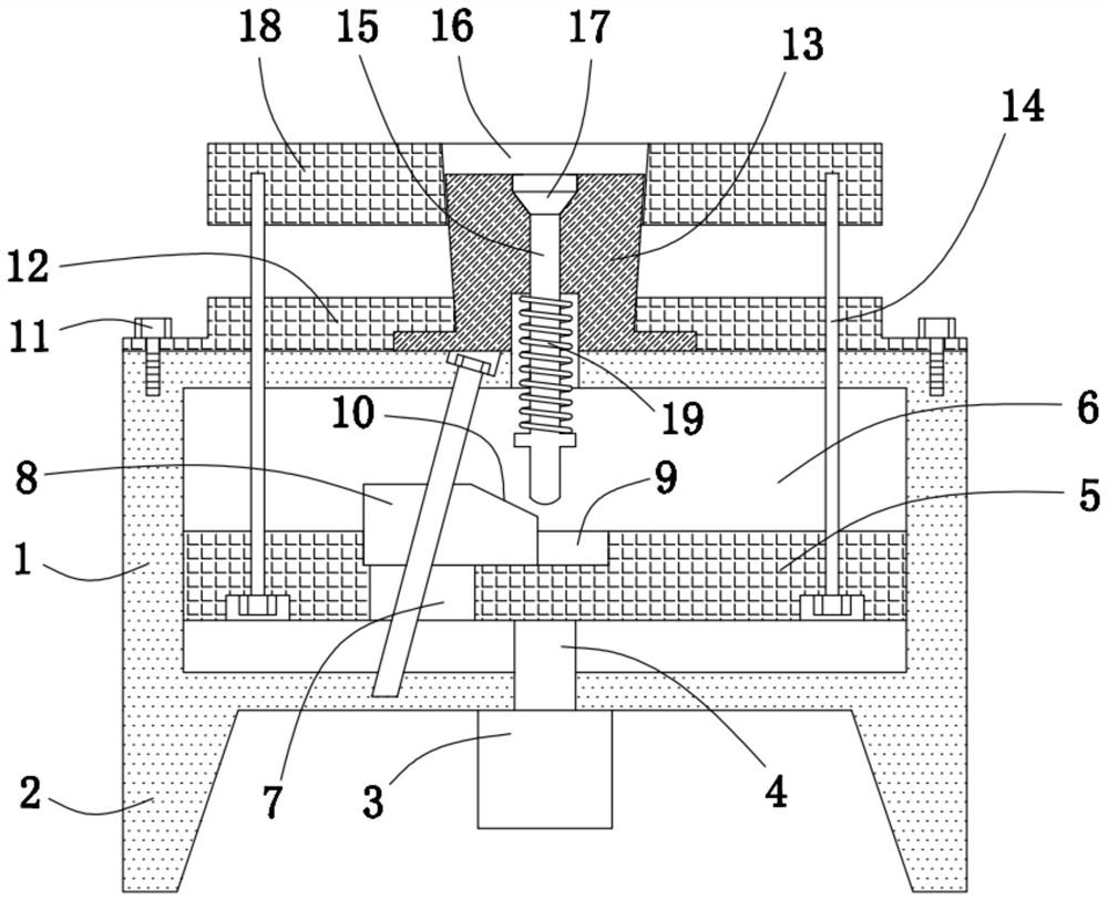
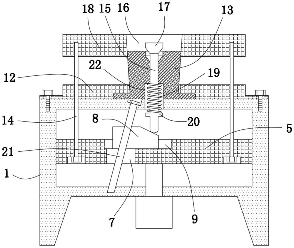
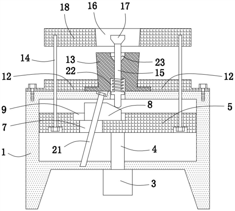
[0028] The present invention provides such as Figure 1-3 A molding die for mechanical manufacturing, comprising a workbench 1, a lifting seat 5 is provided in a cavity 6 inside the workbench 1, a cylinder 3 is installed in the middle of the lower end of the workbench 1, and the output end of the cylinder 3 The piston rod 4 extends into the cavity 6 and is connected to the middle part of the lower end of the lifting seat 5. A moving block 8 is slidingly connected in the chute 9 at the upper end of the lifting seat 5. The upper right end of the moving block 8 is provided with an inclined surface. 10. The bottom of the chute 9 is also provided with a through hole 7;

[0029] The left side of the cavity 6 is also provided with a polished rod 21 that is inclined to the left and right, and the lower end of the polished rod 21 passes through the moving block 8 and the through hole 7 in sequence;

[0030] The connecting rods 14 at both ends of the lifting seat 5 stretch out from the...


PUM


Abstract

The invention discloses a forming die for mechanical manufacturing. The forming die comprises a workbench, wherein a piston rod at the output end of an air cylinder extends into a cavity and is connected to the middle part of the lower end of a lifting seat, a moving block is connected into a sliding groove in the upper end of the lifting seat in a sliding mode, and the lower end of a polished rodpenetrates through the moving block and a through hole in sequence; and connecting rods at the two ends of the lifting seat are fixedly connected to the lower end of a forming seat after extending out of the upper end of the workbench, a forming cavity is formed in the middle part of the forming seat, and the lower end of a die releasing rod penetrating through the middle part of a die releasingbase enters into the cavity after extending out of the interior of a spring. According to the forming die for mechanical manufacturing, the die releasing base can rapidly and accurately enter into theforming cavity, and a die releasing ejection block is completely contained in a containing groove, so that a space capable of being used for punch forming is conveniently formed in the forming cavity, and punch forming of a workpiece raw material is facilitated; and during die releasing, the upper end of the die releasing base is gradually disengaged from the forming cavity, and the die releasingejection block extends out of the containing groove so that a formed workpiece can be rapidly released from the forming cavity.

Description

technical field [0001] The invention belongs to the technical field of moulds, and in particular relates to a molding die for mechanical manufacturing and a molding processing method thereof. Background technique [0002] Forming molds, also known as molds, are molds made in proportion to the shape and structure of the object, and the material is made into a tool of a certain shape by pressing or pouring. The existing forming die cannot quickly form a space for stamping and forming when it is in use, and it often cannot quickly and smoothly separate the forming workpiece from the die when it is demolded. Therefore, we propose a forming die for mechanical manufacturing and its A molding processing method to solve the problems mentioned in the background art above. Contents of the invention [0003] The object of the present invention is to provide a molding die for mechanical manufacturing and a molding processing method thereof, so as to solve the problems raised in the a...

Claims


Application Information

Patent Timeline
Patent Type & Authority Applications(China)
IPC IPC(8): B21D22/02B21D45/02
CPCB21D22/02B21D45/02
Inventor 曹彦博李煜张佩
Owner WUHAN UNIV OF TECH
Why Eureka
Try Eureka