Automatic cutting device for aluminum profile processing

An automatic cutting device and aluminum profile processing technology, applied in the direction of sawing machine, metal processing equipment, sawing machine accessories, etc., can solve the problems of low processing efficiency, short service life, low safety performance, etc., to improve production efficiency and The effect of production quality, liberating manpower, and ensuring processing accuracy

Pending Publication Date: 2020-09-22
河南欣柯奕舟重工科技有限公司
View PDF0 Cites 2 Cited by
  • Summary
  • Abstract
  • Description
  • Claims
  • Application Information

AI Technical Summary

Problems solved by technology

[0002] Traditional wooden door and window materials have disadvantages such as high density, high brittleness, short service life, and low safety performance, while traditional metal door and window materials have high safety performance, but their appearance is not elegant enough, and they have the disadvantages of high cost. More and more families use aluminum alloy doors and windows
The processing of aluminum profile doors and windows requires operations such as cutting and punching of aluminum profiles. The door and window frames need to be assembled and combined with multiple aluminum profiles, so the two ends of the aluminum profiles are different slopes, so the cutting directions of the two ends of the aluminum profiles are also different. Existing The slitting of aluminum profiles in the technology is generally cut separately by cutting equipment. Only by manually adjusting the length of the aluminum profile and its deflection angle with the tool can ensure that the aluminum profile meets the required requirements, so the processing efficiency is not high.

Method used


Image

  • Automatic cutting device for aluminum profile processing
  • Automatic cutting device for aluminum profile processing
  • Automatic cutting device for aluminum profile processing

Examples


Embodiment Construction

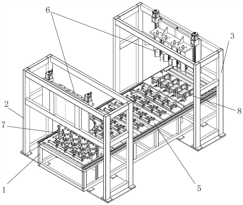
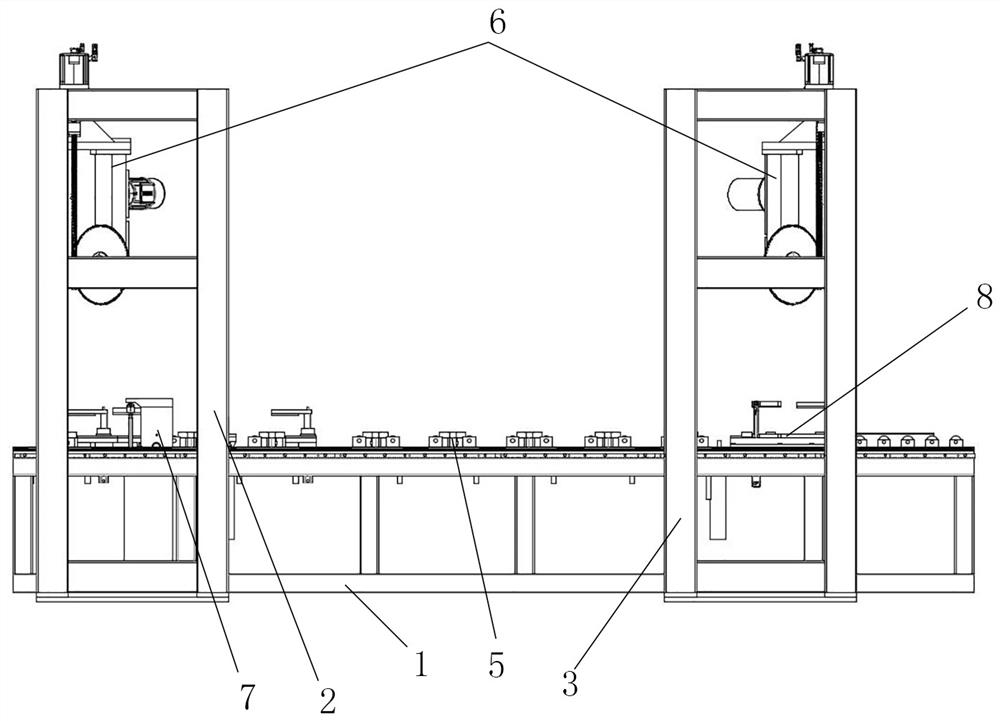
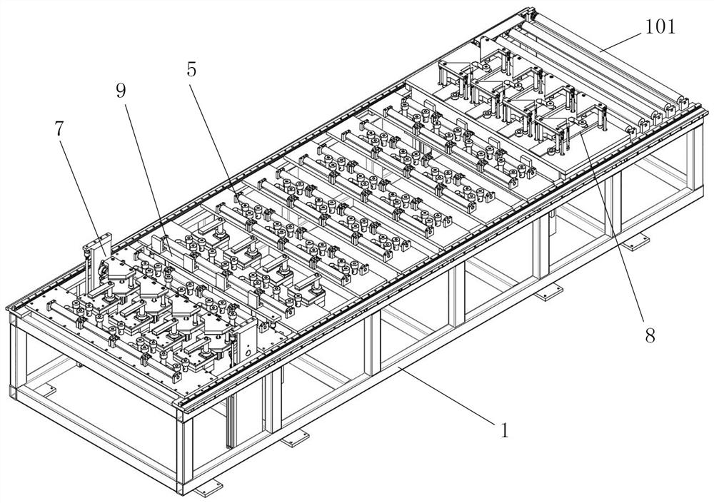
[0036] As shown in the figure: an automatic cutting device for aluminum profile processing, including a conveying frame 1, an end cutting frame 2, a cutting frame 3 and a pushing cart 4, and the pushing cart 4 is installed on the conveying frame 1 and can be transported along the The frame 1 moves, and the conveying frame 1 is equipped with a clamping mechanism for clamping aluminum profiles. Along the processing and conveying direction, the conveying frame 1 is provided with a plurality of supporting and clamping mechanisms 5 for horizontally supporting and laterally movable clamping of aluminum profiles. , the end cutting frame 2 and the slitting frame 3 are all erected above the conveying frame 1, and a plurality of cutting parts 6 for cutting aluminum profiles are installed on the end cutting frame 2 and the slitting frame 3, and the aluminum profiles are composed of multiple After a supporting and clamping mechanism 5 is horizontally supported and movable and clamped, one ...


PUM


Abstract

The invention relates to the technical field of aluminum profile processing equipment, and in particular relates to an automatic cutting device for aluminum profile processing. The automatic cutting device comprises a conveying frame, an end cutting frame, a cutting frame and a material pushing vehicle. Multiple aluminum profiles are placed on the conveying frame and are supported and clamped respectively by multiple supporting and clamping mechanisms to the state parallel to a processing and conveying direction. After the multiple aluminum profiles are clamped and adjusted by a clamping mechanism on the material pushing vehicle to a state of being flat at the end, the aluminum profiles are driven to move and adjust in the length direction of the conveying frame, and the front ends of thealuminum profiles are cut by a cutting piece on the end cutting frame at the end cutting frame. After the aluminum profiles are driven by the material pushing vehicle to move for a long certain length, the aluminum profiles are cut by a cutting piece on the cutting frame at the cutting frame. The cutting pieces on the cutting frame and the end cutting frame can be adjusted so that the length and the deflections of the two end faces of the cut aluminum profiles meet the requirements. The production efficiency is greatly improved.

Description

technical field [0001] The invention relates to the technical field of aluminum profile processing equipment, in particular to an automatic cutting device for aluminum profile processing. Background technique [0002] Traditional wooden door and window materials have disadvantages such as high density, high brittleness, short service life, and low safety performance, while traditional metal door and window materials have high safety performance, but their appearance is not elegant enough, and they have the disadvantages of high cost. More and more families use aluminum alloy doors and windows. The processing of aluminum profile doors and windows requires operations such as cutting and punching of aluminum profiles. The door and window frames need to be assembled and combined with multiple aluminum profiles, so the two ends of the aluminum profiles are different slopes, so the cutting directions of the two ends of the aluminum profiles are also different. Existing The slitti...

Claims


Application Information

Patent Timeline
Patent Type & Authority Applications(China)
IPC IPC(8): B23D45/10B23D47/04B23D47/08B23D59/00
CPCB23D45/10B23D47/04B23D47/042B23D47/08B23D59/006
Inventor 汪建欣汪柯
Owner 河南欣柯奕舟重工科技有限公司
Why Eureka
Try Eureka