Automatic grabbing device for DCT gearbox valve body friction force

A grabbing device and friction force technology, which is applied in the field of DCT transmission valve body friction automatic grabbing device, can solve the problems of high failure rate and scrap rate, large spreader limitations, and inability to clamp and hoist, etc., to achieve increased The effect of success rate, guaranteed accuracy and improved precision

Active Publication Date: 2020-09-22
ANHUI JEE AUTOMATION EQUIP CO LTD
View PDF9 Cites 1 Cited by
  • Summary
  • Abstract
  • Description
  • Claims
  • Application Information

AI Technical Summary

Problems solved by technology

This method of manual hoisting and then press-fitting has a high failure rate and scrap rate, and this type of sling has relatively large limitations. When the valve body sinks into the DCT transmission case as a whole, the sling has no side clamping points and cannot Clamping and lifting

Method used


Image

  • Automatic grabbing device for DCT gearbox valve body friction force
  • Automatic grabbing device for DCT gearbox valve body friction force
  • Automatic grabbing device for DCT gearbox valve body friction force

Examples


Embodiment Construction

[0039] In order to make the purpose, technical solutions and advantages of the embodiments of the present invention clearer, the technical solutions in the embodiments of the present invention will be clearly and completely described below in conjunction with the embodiments of the present invention. Obviously, the described embodiments are part of the present invention Examples, not all examples. Based on the embodiments of the present invention, all other embodiments obtained by persons of ordinary skill in the art without creative efforts fall within the protection scope of the present invention.

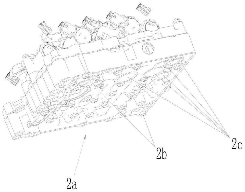
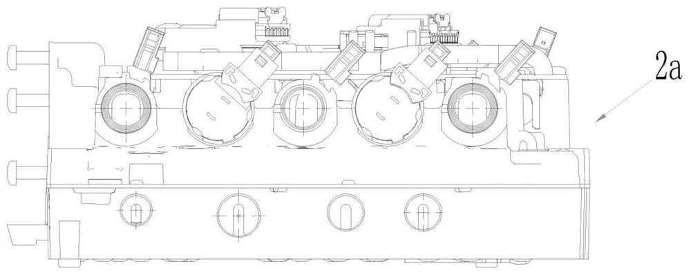
[0040] Figure 4The structure of the top surface of the valve body 2a is shown, and the top surface of the valve body is provided with bolt holes 1'-14' and process bosses 15'-21'.

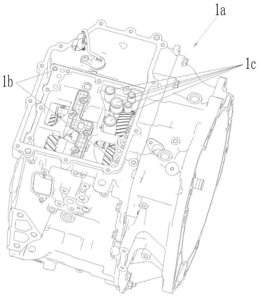
[0041] Please refer to Figure 1 to Figure 13 , the DCT gearbox valve body friction automatic grasping device of this embodiment, the valve body is assembled with the DCT transmission case with the...


PUM


Abstract

The invention provides an automatic grabbing device for DCT gearbox valve body friction force. The automatic grabbing device for the DCT gearbox valve body friction force comprises two sets of drivingassemblies arranged at the top of a mounting plate, a pair of linear guide rail assemblies, four sets of friction clamping pin assemblies, four sets of adjusting mechanisms, three sets of counter-force supporting column assemblies, two positioning pins, two sets of pressing block assemblies and three sets of laser displacement sensor assemblies, the pair of linear guide rail assemblies, the foursets of friction clamping pin assemblies, the four sets of adjusting mechanisms, the three sets of counter-force supporting column assemblies, the two positioning pins, the two sets of pressing blockassemblies and the three sets of laser displacement sensor assemblies are arranged at the bottom of the mounting plate; and a friction force structure formed by the four sets of friction clamping pinassemblies, the pair of linear guide rails and the two sets of driving assemblies automatically grabs a valve body by utilizing the friction force, the two positioning pins are used for positioning the position of the valve body on the automatic friction force grabbing device, the three counter-force supporting columns are used as pressing heads for transmitting the valve body box closing press-fitting force and can play a role in end face positioning, the three laser displacement sensors cooperatively work at three positions to detect the levelness and the in-place state of the valve body, and the two pressing block assemblies are used for preventing the valve body from being lifted when the device is reset after the valve body is closed. The automatic grabbing device for the DCT gearboxvalve body friction force can provide a new simple and effective idea for closing the valve body.

Description

technical field [0001] The invention relates to the technical field of automobile manufacturing, and more specifically relates to an automatic grasping device for DCT gearbox valve body friction force. Background technique [0002] HCU (hydraulic system, referred to as valve body) is one of the important components in the DCT transmission, and its assembly quality directly affects the overall performance of the transmission. The HCU box closing process needs to align two positioning pins and five oil pump valve body connecting pipes at the same time. Such as figure 1 As shown, the two positioning pin holes on the side of the DCT transmission away from the case ( figure 1 Middle 1b), five oil pump valve body connecting pipes ( figure 1 in 1c); if figure 2 and image 3 As shown, the two positioning pins on the valve body side ( figure 2 Middle 2b), five connecting pipe installation holes ( figure 2 In 2c), it cooperates with the DCT transmission side away from the ca...

Claims


Application Information

Patent Timeline
Patent Type & Authority Applications(China)
IPC IPC(8): B23P19/00B23P19/10
CPCB23P19/007B23P19/105
Inventor 刘蕾韩光明李国春
Owner ANHUI JEE AUTOMATION EQUIP CO LTD
Why Eureka
Try Eureka