
New energy automobile charging pile with self-retractable charging wire

A technology of new energy vehicles and charging lines, which is applied in the direction of electric vehicle charging technology, electric vehicles, charging stations, etc., can solve the problems of electric shock hazard and inconvenient charging line retraction, and achieve the effect of preventing electric shock hazards

Active Publication Date: 2020-09-22
WORKERSBEE ELECTRONICS TECH HLDG SUZHOU CO LTD
View PDF6 Cites 3 Cited by
  • Summary
  • Abstract
  • Description
  • Claims
  • Application Information

AI Technical Summary

Problems solved by technology

[0005] The purpose of the present invention is to provide a self-retractable charging pile for new energy vehicles that is convenient for charging cables and has high safety performance for the problems that the charging cables are inconvenient to retract and there is a risk of electric shock

Method used


Image

  • New energy automobile charging pile with self-retractable charging wire
  • New energy automobile charging pile with self-retractable charging wire
  • New energy automobile charging pile with self-retractable charging wire

Examples


Embodiment 1

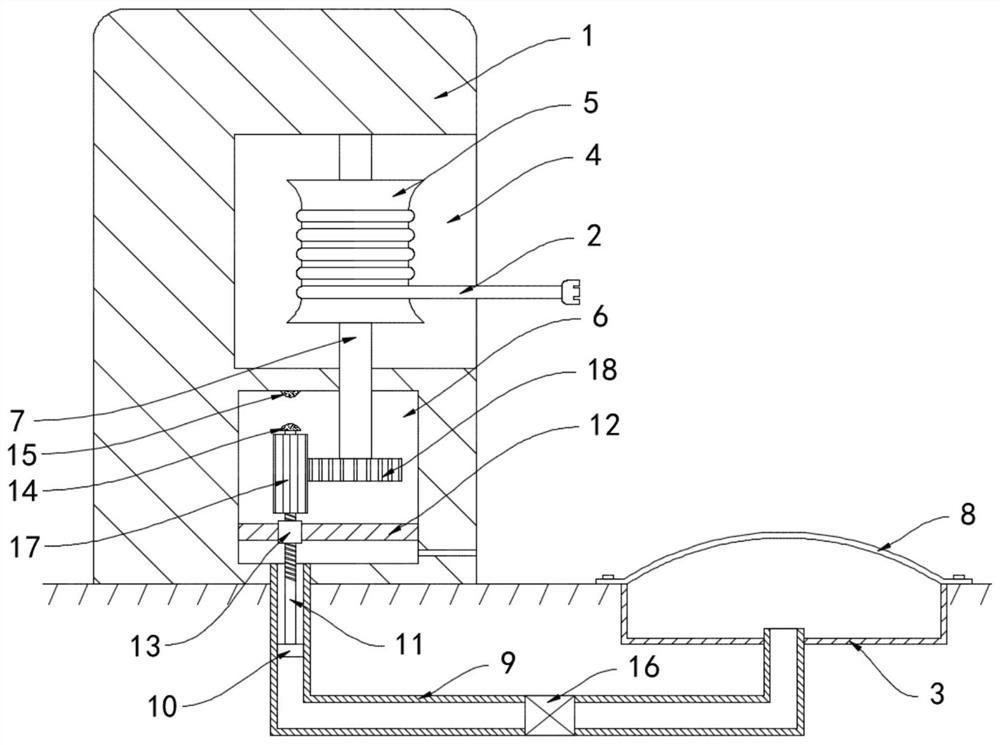
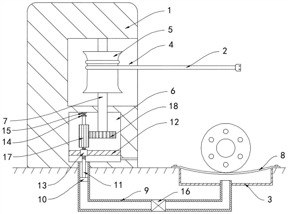
[0022] like Figure 1-2 As shown, a new energy vehicle charging pile with a self-retractable charging line includes a pile body 1 and a charging line 2, a sealed box 3 is embedded in the ground on one side of the pile body 1, and a The retracting groove 4 is provided with a vertically arranged retracting wheel 5 in the retracting groove 4, and the driving cavity 6 is provided in the pile body 1. The lower end of the retracting wheel 5 is coaxially fixedly connected with a rotating shaft 7, and the lower end of the rotating shaft 7 extends Set in the driving chamber 6.

[0023] The upper surface of the sealing box 3 is fixedly connected with an identification plate 8, and the identification plate 8 is an elastic plate whose middle part is upwardly arched. The upper surface of the identification plate 8 protrudes from the ground and is arranged. One end of the air pipe 9 close to the drive chamber 6 is arranged in the vertical direction. A slide plug 10 is connected to the air ...

Embodiment 2

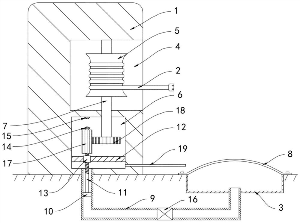
[0031] like image 3 As shown, the difference between the present embodiment and the first embodiment is that: the side wall of the drive chamber 6 is communicated with an exhaust pipe 19 , and the other end of the exhaust pipe 19 extends to the identification plate 8 .

[0032] In this embodiment, when the sliding plug 10 moves upwards under the action of air pressure, the air in the drive chamber 6 is squeezed and blown on the surface of the sign plate 8 through the exhaust pipe 19, blowing out the dust and foreign matter on the surface of the sign plate 8 to improve It improves the recognition of the sign board and facilitates the standard parking of vehicles.


PUM


Abstract

The invention belongs to the field of new energy, and especially relates to a new energy automobile charging pile with self-retractable charging wire. The charging pile comprises a pile body and the charging wire. A sealing box is embedded in the ground on one side of the pile body; a winding groove is formed in the side wall of the pile body; a winding wheel which is vertically arranged is arranged in the winding groove; a driving cavity is formed in the pile body; the lower end of the winding wheel is coaxially and fixedly connected with a rotating shaft; the lower end of the rotating shaftextends into the driving cavity; an identification plate is fixedly connected to the upper surface of the sealing box; the identification plate is an elastic plate with the middle arched upwards; theupper surface of the identification plate protrudes out of the ground; the sealing box is communicated with the driving cavity through an air guide pipe; and the end, close to the driving cavity, of the air guide pipe is arranged in the vertical direction. The charging wire can be automatically retracted, troubles to workers and traffic caused by random placement of the charging wire are avoided,the charging wire is in a power-off state when not in use, and the problem of electric shock danger caused by mistaken touch of pedestrians can be prevented.

Description

technical field [0001] The invention belongs to the field of new energy, and in particular relates to a new energy vehicle charging pile with self-retractable charging lines. Background technique [0002] With the advancement of technology and living standards, the pollution of the natural environment on which human beings depend is becoming increasingly serious. In order to solve the problem of environmental pollution, new energy vehicles have become an important measure to replace traditional fuel vehicles. With the development of new energy vehicles Widely used, the charging pile industry for new energy vehicles is also on the rise. [0003] At present, the charging piles of new energy vehicles generally have the problem that the charging cables are too long and inconvenient to store. The randomly wound charging cables bring great troubles to the staff. When using them, the charging cables need to be pulled out of the charging piles to finish charging. , it is necessary ...

Claims


Application Information

Patent Timeline
Patent Type & Authority Applications(China)
IPC IPC(8): B60L53/31B60L53/18B60L53/14B65H75/44
CPCB60L53/31B60L53/18B60L53/14B65H75/44Y02T90/14
Inventor 陈大英
Owner WORKERSBEE ELECTRONICS TECH HLDG SUZHOU CO LTD
Learn More