
Method for operating device having internal combustion engine and electric machine

An internal combustion engine, operating range technology, applied in the field of computer programs, which can solve problems such as poor compensation

Pending Publication Date: 2020-09-22
ROBERT BOSCH GMBH
View PDF0 Cites 0 Cited by
  • Summary
  • Abstract
  • Description
  • Claims
  • Application Information

AI Technical Summary

Problems solved by technology

[0004] Therefore, precisely for internal combustion engines with a small number of cylinders, such as are used especially in motorcycles, the compensation of these rotational speed fluctuations can only be performed poorly.

Method used


Image

  • Method for operating device having internal combustion engine and electric machine
  • Method for operating device having internal combustion engine and electric machine
  • Method for operating device having internal combustion engine and electric machine

Examples


Embodiment Construction

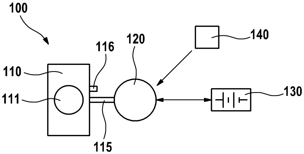
[0039] exist figure 1 A device 100 with an internal combustion engine 110 and an electric machine 120 is schematically shown, with which the method according to the invention can be carried out. Internal combustion engine 110 is designed as an exemplary internal combustion engine with cylinders 111 and crankshaft 115 .

[0040] Electric machine 120 is torque-transmittingly coupled to crankshaft 115 and thus also torque-transmittingly coupled to internal combustion engine 110 . Furthermore, the electric machine 120 is electrically connected to an energy store 130 , which can be a battery, for example, ie electrical energy can flow from the electric machine 120 to the energy store 130 and vice versa. Furthermore, the vehicle electrical system can be electrically connected to energy storage device 130 .

[0041] By means of the computing unit 140 designed as a controller, the electric machine 120 can be controlled accordingly, that is to say a torque-absorbing or generator-like...


PUM


Abstract

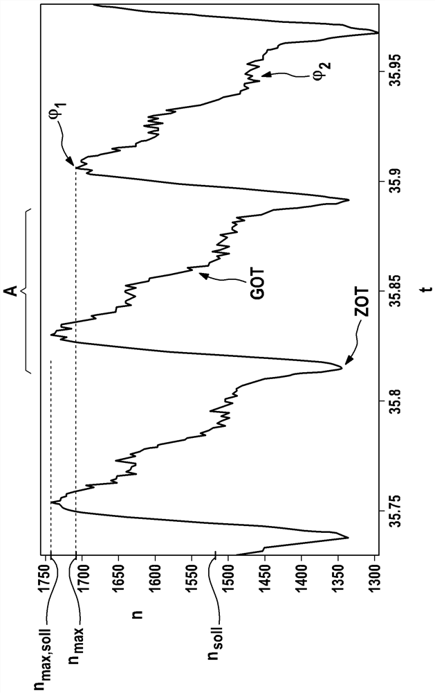
The invention relates to a method for operating a device having an internal combustion engine and an electric machine. The internal combustion engine has a crankshaft and the electric machine is coupled to the crankshaft in a torque-transmitting manner, the electric machine is electrically connected to an energy accumulator, wherein a current value (nmax) of the rotational speed (n) of the crankshaft is determined within a predetermined operating range of the internal combustion engine within a working cycle (A) of cylinders of the internal combustion engine at a predetermined crankshaft angle(1).

Description

technical field [0001] The invention relates to a method for operating a device having an internal combustion engine and an electric machine, wherein the internal combustion engine has a crankshaft and the electric machine is torque-transmittingly coupled to the crankshaft, and the electric machine is electrically connected to an energy store. And the invention also relates to a computing unit and a computer program for implementing the method. Background technique [0002] In internal combustion engines, the rotational speed is increased by the kinetic energy generated during the working stroke, and the rotational speed is reduced by the subsequent exhaust stroke, intake stroke and compression stroke. This also produces certain rotational speed fluctuations within the working cycle of the cylinders of the internal combustion engine. [0003] The higher the number of cylinders of the internal combustion engine for which the working strokes are also offset relative to one an...

Claims


Application Information

Patent Timeline
IPC IPC(8): B60W20/13B60W10/06B60W10/08B60W10/26F02D41/00F02D37/02F02D29/06
CPCB60W10/06B60W10/08B60W10/26B60W20/13F02D29/06F02D37/02F02D41/0002B60W30/20B60W2030/206B60W2710/0644F02D31/001F02D41/0097F02D41/0205F02D41/083F02D41/1497F02D2200/1002F02D2200/101F02D2200/1012F02D2200/503F02D2250/24
Inventor S.格罗德J.米勒W.费希尔
Owner ROBERT BOSCH GMBH
Learn More