
Rotor structure of rotary valve for regenerative oxidation furnace

A technology of rotor structure and oxidation furnace, applied in the direction of valve shell structure, incinerator, valve details, etc., can solve the problems of complex structure of inner shaft 52, inconvenient disassembly and assembly, and inconvenient processing, so as to save materials and processing costs, Easy processing and easy assembly

Pending Publication Date: 2020-09-22
SHANGHAI SHENGJIAN ENVIRONMENTAL SYST TECH
View PDF0 Cites 0 Cited by
  • Summary
  • Abstract
  • Description
  • Claims
  • Application Information

AI Technical Summary

Problems solved by technology

The air distribution valve rotor with this structure is inconvenient to disassemble, the overall weight is heavy, and the structure of the inner shaft 52 is complicated, which is not easy to process

Method used


Image

  • Rotor structure of rotary valve for regenerative oxidation furnace
  • Rotor structure of rotary valve for regenerative oxidation furnace
  • Rotor structure of rotary valve for regenerative oxidation furnace

Examples


Embodiment 1

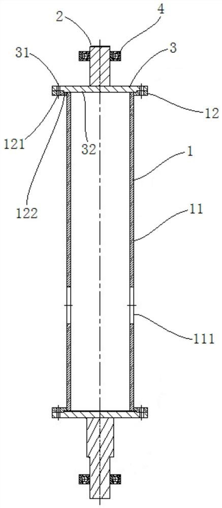
[0033] Such as figure 2 As shown, this embodiment provides a rotor structure for a rotary valve for a regenerative oxidation furnace, which includes a hollow sleeve 1 with a tube body 11 and two shaft heads 2, and the hollow sleeve 1 also includes two The first connecting piece 12 connected to the two ends of 11, the ends of the two shaft heads 2 are respectively connected with two second connecting pieces 3, and the two first connecting pieces 12 are detachable from the two second connecting pieces 3 respectively. connect. In this embodiment, the rotor structure of the rotary valve for the regenerative oxidation furnace is detachably connected with the two first connecting pieces 12 and the two second connecting pieces 3 respectively, so as to realize the connection between the two shaft heads 2 and the hollow sleeve 1 respectively. The two ends are connected. This connection method is convenient for disassembly and assembly, and saves the part of the shaft located in the h...

Embodiment 2

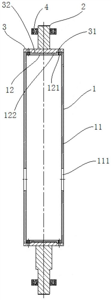
[0042] Such as image 3 As shown, this embodiment is based on the first embodiment above, and the difference is that in this embodiment, the first connecting piece 12 is fixedly connected to the inner wall of the pipe body 11, and the first connecting hole 121 is a threaded hole, and the bolt is connected to the first connecting piece. The side wall of the hole 121 is threaded. In this embodiment, the first connection piece 12 is located inside the pipe body 11 to save space, and the structure is more compact, and the first connection hole 121 on the first connection piece 12 is a threaded hole. When assembling, the bolt passes through the second connection The second connection hole 31 on the piece 3 is directly threaded with the side wall of the first connection hole 121, thereby realizing the detachable connection between the first connection piece 12 and the second connection piece 3, which is easy to operate and convenient for the first Assembly between the connecting pi...


PUM


Abstract

The invention provides a rotor structure of a rotary valve for a regenerative oxidation furnace. The rotor structure comprises a hollow sleeve with a tube body and two shaft heads, wherein the hollowsleeve also comprises two first connecting pieces connected with two ends of the tube body respectively; two second connecting pieces are connected with the ends of the two shaft heads respectively; and the two first connecting pieces are detachably connected with the two second connecting pieces respectively. The rotor structure of the rotary valve for the regenerative oxidation furnace is detachably connected with the two second connecting pieces through the two first connecting pieces, so that the two shaft heads are connected with the two ends of the hollow sleeve respectively. In this connection manner, disassembly and assembly are facilitated, the part of a shaft in the hollow sleeve is omitted, materials and machining cost are saved, and weight is reduced; meanwhile, the adopted shaft heads are simple in structure and convenient to machine; and the interior of the hollow sleeve is of an integral cavity structure and can be used for gas flow, so that the air flow space in the hollow sleeve is increased, and the air flow effect is improved.

Description

technical field [0001] The invention relates to a regenerative oxidation furnace, in particular to a rotor structure of a rotary valve for the regenerative oxidation furnace. Background technique [0002] The English abbreviation of the regenerative exhaust gas treatment device is RTO, and its working principle is: directly heat the organic waste gas to a high temperature above 800°C to oxidize and decompose the organic waste gas. The rotary RTO, also known as the rotary regenerative oxidation furnace, works on the principle of oxidizing combustible waste gas into corresponding oxides and water at high temperature, thereby purifying the waste gas and recovering the heat released when the waste gas decomposes. [0003] At the same time, the rotary air distribution valve is the heart of the rotary RTO. When the gas distribution valve is working, it rotates smoothly to transport the exhaust gas evenly to different sectors of the heat storage area, so as to ensure the stability...

Claims


Application Information

Patent Timeline
Patent Type & Authority Applications(China)
IPC IPC(8): F23G7/06F23G5/44F16K27/00F16K51/00
CPCF16K27/00F16K51/00F23G5/44F23G7/06
Inventor 张伟明陈佑星汪哲
Owner SHANGHAI SHENGJIAN ENVIRONMENTAL SYST TECH
Features
  • Generate Ideas
  • Intellectual Property
  • Life Sciences
  • Materials
  • Tech Scout
  • Unparalleled Data Quality
  • Higher Quality Content
  • 60% Fewer Hallucinations
Learn More